Cooling System Menu
- Introduction to Air Cooling
- Water-Cooled Air Conditioner
- Chest Freezer Air Conditioner
For years, I wanted a perfectly controlled environment for growing highland and ultra-highland Nepenthes pitcher plants, but these carnivorous plants need humid conditions with very mild temperatures and cool nights. Commercial products are not exactly available to accomplish night air temps down to around 50°F, so I have experimented with a wide variety of different DIY projects to build my own cooling system to reach these conditions.
While my favorite plants are highland neps, my advice on air / water cooling can honestly be helpful for creating a growing area for any plants or possibly even animals that have specific environmental requirements. Most Heliamphora appreciate cold nights into the 50s. Cephalotus also likes cooler nights. Even outside of carnivorous plants, anything that grows in montane cloud forests, like orchids, will also have similar needs. You could technically even create an arctic-like climate for a penguin with a more beefed-up water cooling system than the one I will show you how to build here.
Although I have figured out two methods that do work great to turn hot air into cold air, most of my attempts at creating a system to automate the cooling of my highland chamber ended in at least partial failure. Even if something worked, it was often not powerful enough to put out cold air for a full 10 hour night and/or it simply wasn’t able to reach 50°F. I was also going for something that was automated because things like freezing water bottles or filling a water reservoir with ice every night are no fun to do long-term.
The purpose of this cooling system guide is to not only teach you what does work but also what doesn’t work (and why). Armed with this knowledge, you will be able to create your own system that is capable of dropping the temperature of any enclosed area to any target temperature you want, even below-freezing (my exact water cooling method can deliver temps roughly down to 10°F).
On top of this essential knowledge, I’m also going to walk you through exactly how I created two different kinds of cooling systems (water cooling and freezer based cooling) so you can make something similar that will work for your own needs. However, please be sure to read this entire article to make sure your creation will actually work as intended – things like cooling power, ambient temps, insulation and growing area can drastically alter your needs from your cooling system.
It is actually a lot easier to warm things up than it is to cool them down – this is because you can add heat or remove heat but you can’t actually add cold. When you want to make something cold, you accomplish this by removing warmth. Remember that because even the best cooling system will be worthless if you do not put your heat somewhere that it can’t reheat what you want to cool.
Commercial Aquarium Water Chillers
Anyone that is new to water cooling will likely end up considering buying a commercially available water chiller sold for aquariums. However, I would strongly recommend against using these if you want to cool air. I was highly considering purchasing one of these at one point, but I did a lot of research and realized that it wasn’t the best choice for what I wanted to do.
One of the biggest things that held me back from getting a water chiller was the price. To get one with the same BTUs as a $120 window AC unit, it would cost somewhere between $500 and $1,000.
Another potential problem is that the aquarium chillers didn’t seem to be used to lower water temperatures a lot. Most of them are intended to be used on fairly large volumes of water to cool that water by small amounts – often less than 10°F total (so 80°F water might get cooled to 70°F). To drop a grow chamber from 75°F down to 50°F, you’re going to need water that is around 37°F – 40°F. That means you may need a water chiller that can drop temps by 30°-35° (depending on your ambient temps – mine are about 73°F).
As I said before, I did a lot of research to find out if these would actually be able to work under those conditions. There was not a lot of information out there about people that had tried to do what I wanted to do, so reviews were extremely limited.
Some hydroponics growers were using them to cool air, but they were cooling the air exhaust from a metal halide lights and they were often only going for water about 10° colder. In fact, many of them that purchased lower power water chillers (1/10hp, 1/8hp, 1/5hp, and 1/4hp) were not even able to get water 10° below ambient temps. The best results looked to be using 1/2hp, 1hp or even larger chillers, but these get obscenely expensive.
I also researched why these aquarium chillers were so much more expensive compared with an air conditioner, since the same basic equipment is used for both. I found out that it is because of the metals used in each. Aquarium fish, especially expensive saltwater tropical reef fish, are very sensitive to certain kinds of metal commonly used in air conditioners (copper is the biggest potential killer). Even though this is somewhat similar to carnivorous plants (they too can be killed from copper exposure in the soil), the way I would be using the cold water to cool air never allows that water to come in contact with the plants. This means that for air cooling purposes, you should NOT waste your money on an aquarium water chiller – you can do the same thing for about 20% the price if you use my DIY water chiller method on this page.
Cooling with Air Conditioners
Air conditioning (ACs) are the obvious choice for making air colder, but most affordable units really won’t do a great job if you want temps below 60°F. Most people aren’t comfortable when it is that cold, so an AC really isn’t designed to cool an area below that mark.
Another big problem with an AC is that it will remove a lot of humidity from your air, which is actually the opposite of what you want to happen at night in a highland Nepenthes chamber – you want cold air and high humidity. This single fact is actually a major issue for nearly any cooling system you can put together because when warm, humid air meets a cold surface the water will condensate out of the air onto the cold surface.
With that said, if you were to build a grow chamber and put a window AC unit in one of the walls, you could certainly cool it down at night. However, you may not be able to get as low as 50°F, you would need to constantly pump more humidity into the growing area before that air reaches plants, and that humidity would then get stripped out of the air and put out the back of the AC in the drip pan. This will result in a pretty large puddle of water below the back of the AC unit from just a single night of running (yep, I found this out the hard way). On top of that problem, you would also have hot air coming out of the back that would heat up the room and likely fight the cooling inside of the chamber.
There are other kinds of air conditioners besides window units, but they get more expensive. A portable AC can vent the hot air and water condensation out a duct, but these are expensive and will still not likely reach 50°F or close to it.
Other Creative Options
When people start to think about other commercial products that make things cold like a refrigerator or freezer, they will often consider using them for a cooling system. Yes, I’ve done this too and wasted a bunch of money in the process, so I would like to try to save you those same troubles. The wasted money part obviously sucks, but the worst thing about a creative failure is the disappointment from the wasted time, effort and hopes.
A freezer can potentially work, but only if it is used in one of a limited number of ways. A fridge would only work if the plants were grown inside, although you would still have the issue of humidity being stripped from the air (which would then leak out the bottom of the fridge).
You can also grow plants directly inside of a freezer. I have seen this method done many times for ultra-highland chambers. However, I’m not a fan of this approach for a number of reasons. First, you’re very limited in growing area – the width and length of the freezer interior. Second, when you water it goes to the bottom so you have to drain it on a regular basis.
A freezer gets cold by making the walls cold, so water in the air will also condensate on the walls because they will be colder than the air when the freezer is cooling. This also leads back to the issue of needing the constantly pump more humidity into the air, although you could simply recirculate that water by using the bottom of the freezer as a reservoir.
The next issue is lighting – it either needs to go in the freezer or you need a clear top so it can be outside (outside is best to keep that extra heat out). This basically means that you have to remove the top of the freezer and add your own. Finally, I’m not a big fan of only accessing my plants from above and the freezer restricts access to the plants as well as anything below them. Just as one example, if you have a pump or ultrasonic humidifier in the bottom of the freezer and one broke, you would have to take out all of your plants and shelving to get to them.
Ultimately, the approach to grow plants like N. villosa inside of a freezer can work, but you won’t be growing any giant plants in it. Later in this guide I will talk about another freezer method I have tried that works. As far as a fridge, you yet again run into many of the exact same issues but with even less cooling power, so I really don’t recommend them.
Ambient Room Temperature
Where will you locate your highland grow chamber? This is an important question because you need to consider the natural temperatures of that area to figure out how much cooling power you really need.
For example, my house stays around 70°F – 73°F all year. If I put a box in my house and want to cool that box to 50°F, I need to remove roughly 20°F worth of heat (plus any heat that may be generated by electronics in the growing area, which is fairly minimal at night minus the actual cooling system’s heat exhaust).
With that same example, my garage is a different story. It has somewhat milder temps than outside conditions, but it has massive fluctuations. In the winter it can get into the mid 30s in the garage and in the summer it can be 90-100°F in there.
Using those examples, a grow chamber in my house would need much less cooling power to reach 50°F consistently all year. A grow chamber in the garage would need massive cooling power in the summer and would likely even need some heating in the winter.
Personally, I find that the best place to put a highland Nepenthes grow chamber is in an unheated basement. The more enclosed the basement is by dirt on the outside, the more likely it is to have mild temperatures all year (usually around 60-65°F). The next best place is in any temperature controlled area of your house. An unheated garage often ranks last in terms of temp fluctuations. Ultimately, the more stable and cool of an environment you can put the chamber in, the less cooling power you will need and the less you will spend on electricity to run your cooling system.
Grow Area Insulation & Air Sealing
Another major factor that will affect how much you are able to cool an area is the insulation and ultimately how air-tight is the chamber. The better the sealing and insulation, the less cooling power will be needed and the more efficient the cooling system will run. However, poor insulation and sealing isn’t a complete deal breaker – you simply need a lot more power to cool the area.
With that said, my chamber uses weather stripping around the doors, but it’s not 100% sealed. There are 4″ ducts on each side of the chamber that run during the day for venting, but these are not sealed at night. Those ducts have about 3-4 feet of insulated flexible ducting attached to each side, so that area does seem to keep air from easily escaping the chamber. I also have some insulation around most sides of the box (about 1/2″), but it could certainly be insulated better.
Using the freezer cooling method detailed on this page, my chamber was able to reach about 57°F at night. However, if I threw a couple of blankets over it after the lights went off, it could reach 50°F. This simply means that more insulation and sealing is necessary for a cooling system with less BTUs of cooling power. Personally, I wanted the system automated and didn’t want to deal with covering it each night and uncovering it each morning.
The same chamber using my water cooling method that is also detailed on this page can easily reach 50°F at night, and it could definitely go lower. I actually have had to turn down the fan to it’s lowest setting to keep it from making the area too cold too fast. That same cooling system could cool a much larger area or even turn my highland chamber into an area for ultra-highlanders.
The point here is that you either need good insulation and sealing or a cooling system that can put out a lot of cold air. If you can have all of those things, your system will be more energy efficient.
Cooling Power (BTUs)
How much and how frequently will your setup need cold air delivered to it? A chamber that only needs night cooling has more options than one that could need it during the night and day.
Highland Nepenthes chambers will demand cold nights down to around 50°F, but they also prefer days that do not get too hot. Depending on where you will place your chamber, the lights alone could heat the area to temps above your desired levels. For mine, I shoot to keep days no higher than 75°F. For an ultra-highland setup, you would need even colder nights and cooler days than that.
With either choice, you will likely end up needing the capability to lower temps during the day unless your chamber will be in a cool basement. If you will need cold air at any time, you should go for the water cooling system. The freezer method can deliver cold nights, but it needs the day time to freeze water jugs, so running it a few times during the day will kill the night time cooling efficiency and prevent you from reaching the temps you want.
For these reasons, the water cooling system is much more reliable because it can deliver much more cooling power when needed. The real reason behind it involves the BTUs of the cooling systems. Refrigerators and freezers have a very low BTU, while air conditioners have much higher ratings (even a cheap window AC unit can have 5-10 times the BTU of a large chest freezer).
Even though a fridge / freezer is designed to hold lower temperatures, it is not meant to constantly cool large volumes of air down to those temperatures. In fact, overloading these appliances with a lot of warm air for prolonged periods of time can cause the compressors to burn out and die.
Fan Speed & Duct Size
Basically all air conditioning systems, whether store-bought or self-made, involve a fan passing air over a heat exchanger to cool it. Ultimately, the power of your fan can have a major effect on how much your system can cool the air. Most fans have a CFM rating, which is cubic feet per minute – this represents how much air volume the fan can move each minute. Higher CFM fans will move more air and therefore cool down a larger volume of air faster.
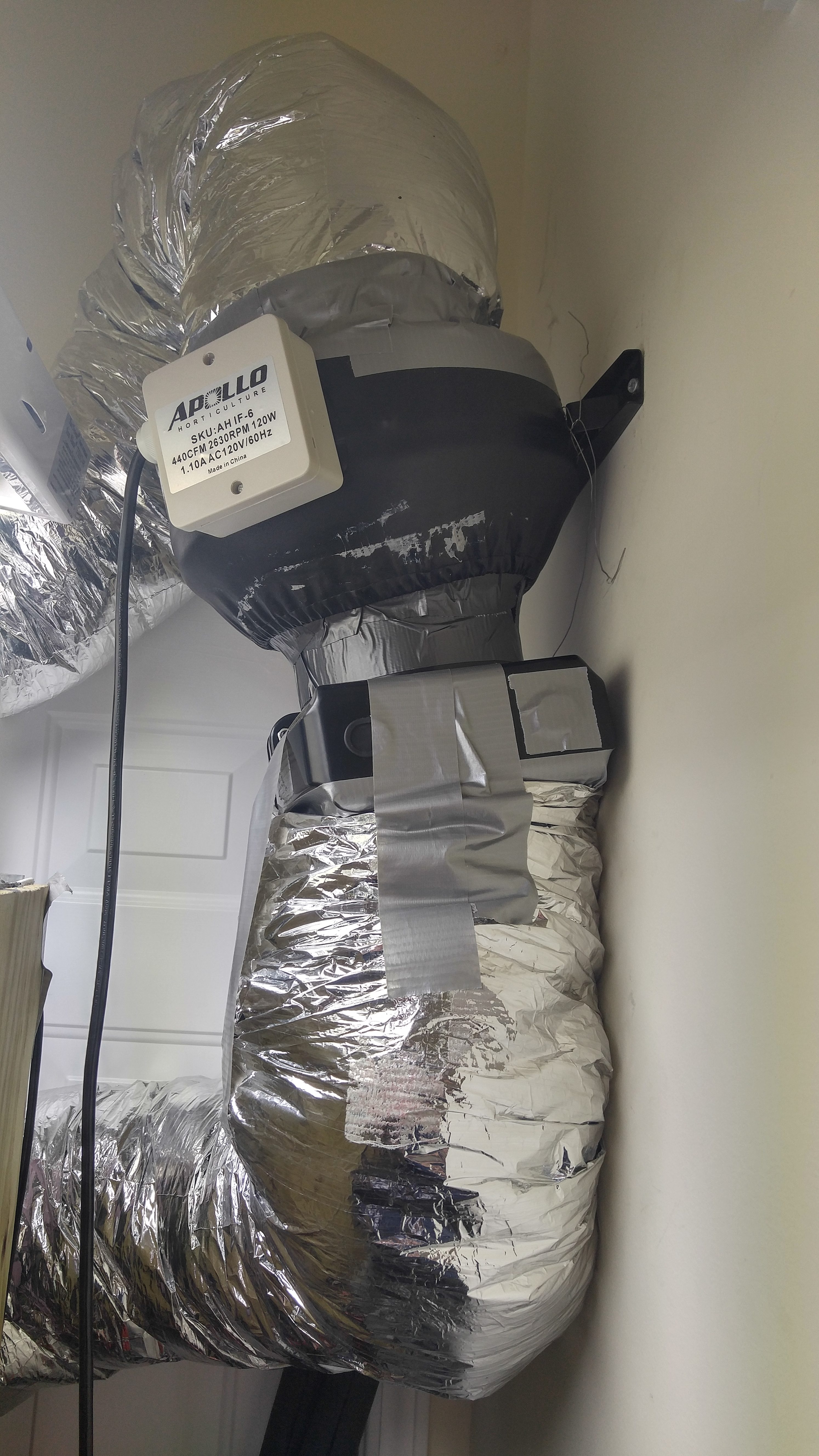
One other factor that drastically affects air volume movement is the diameter of the duct. For a plant growing chamber, especially one that will constantly stay humid like mine, you generally want electronics like these located outside of the grow box so ducts are used to recirculate air. A larger duct will be able to move more air, while a smaller one will move much less. You can typically see this reflected in fan speeds based on their diameter size. For example, 4″ inline fans generally run between 100 – 170 CFM, but a 6″ duct fan can be around 440 CFM. This simply means that the larger the duct, the more cooling capacity it can deliver.
Personally, I recommend having a cooling system fan with a CFM of at least 5 times the cubic feet area. My growing area used with my cooling system is 2′ x 4′ x 2.5′ to give a total of a 20 cubic feet. I have a 440 CFM 6″ fan, which means the fan can recirculate the air volume 22 times per minute. However, my fan has an adjustable speed setting, and I have it very close to the lowest setting. The same fan could easily work for a grow chamber that is 2-4 times larger. With that said, it’s still better to go for a more powerful fan with adjustable speed to be absolutely sure that it still be strong enough.
My heat exchanger is also part of the fan and duct line. I’m using a 6″ Hydro Innovations Ice Box. I read a lot of reviews from hydroponics people that this one wasn’t very strong, but I am very confident that it was because of their under-powered aquarium water chillers. I could easily use the same fan and ice box combo for a much larger growing area than my current 20 cubic feet.
» Air Cooling System Powered By A DIY Water Chiller
I can’t exactly take 100% credit for this homemade AC system because it is the result of many hours of research and trial and error – it is a combination of what I have seen work for others and also what I needed to achieve the temps I wanted with my growing area. Ultimately, if you want to dramatically decrease air temperatures in an enclosed area, I highly recommend this cooling method. Simply put, this system is really versatile and powerful. I use it for creating highland or even ultra-highland Nepenthes grow chambers, but it could be used for many other purposes such as creating a sub-zero liquid cooled computer.
Here are the basics on how this system works…
A window AC unit is slightly modified to become a high-powered water chiller. This maintains a cold water reservoir at a set temperature level – I use RV antifreeze instead of water to allow for lower temps without freezing. A temperature sensor and a thermostat are used to control when the air conditioner turns on and off, which controls the reservoir temperature.
Two water pumps are inside of the reservoir. One of these runs all the time and recirculates water inside of the reservoir to mix it up and keep even temps. The output from that pump is also directed across the heat exchanger from the window AC unit. The second pump turns on when the cooling system is running, and it recirculates water from the reservoir to the Ice Box heat exchanger and back.
That Ice Box heat exchanger then has an inline duct fan connected to one side. Ducts or PVC pipes are then used to connect this fan / ice box combo to the growing area so air can be sucked out of the grow box, pushed through the ice box and back into the grow box.
Another temperature sensor and thermostat is then placed inside of the grow box to control the temps. The one I use detects when the lights are on and allows different day / night settings, so when the lights go out the pump and fan for the cooling system will turn on (I also have ultrasonic humidifiers that turn on with it to ensure the humidity stays high).
For my project, I was trying to cool 20 cubic feet from 75°F down to 50°F during the 10 hour night. What I built is only used at a fraction of it’s total power, so this same design could easily be used for a larger growing area.
If you wanted to create a large walk-in grow chamber, you could easily modify this system with a larger reservoir, more window AC units cooling it, and multiple fans / ice boxes (the multiple ice boxes allow you to have intake and exhaust in multiple locations in the same growing area for more uniform cooling).
Now I’m going to walk you through how I created and built this cooling system.
Below are all of the materials I used for this project. Some of these items are easily found at your local Lowes for affordable prices. Other materials in the list below were not found in local retail stores and were instead purchased on Amazon for convenience, availability and also because they typically had the lowest price. Any items that I recommend getting online through Amazon are linked in the list below to the appropriate product listing on Amazon that I purchased for my project. Anything in the list below that is not linked to an Amazon page was purchased from Lowes.
[cmaz id=”1″]
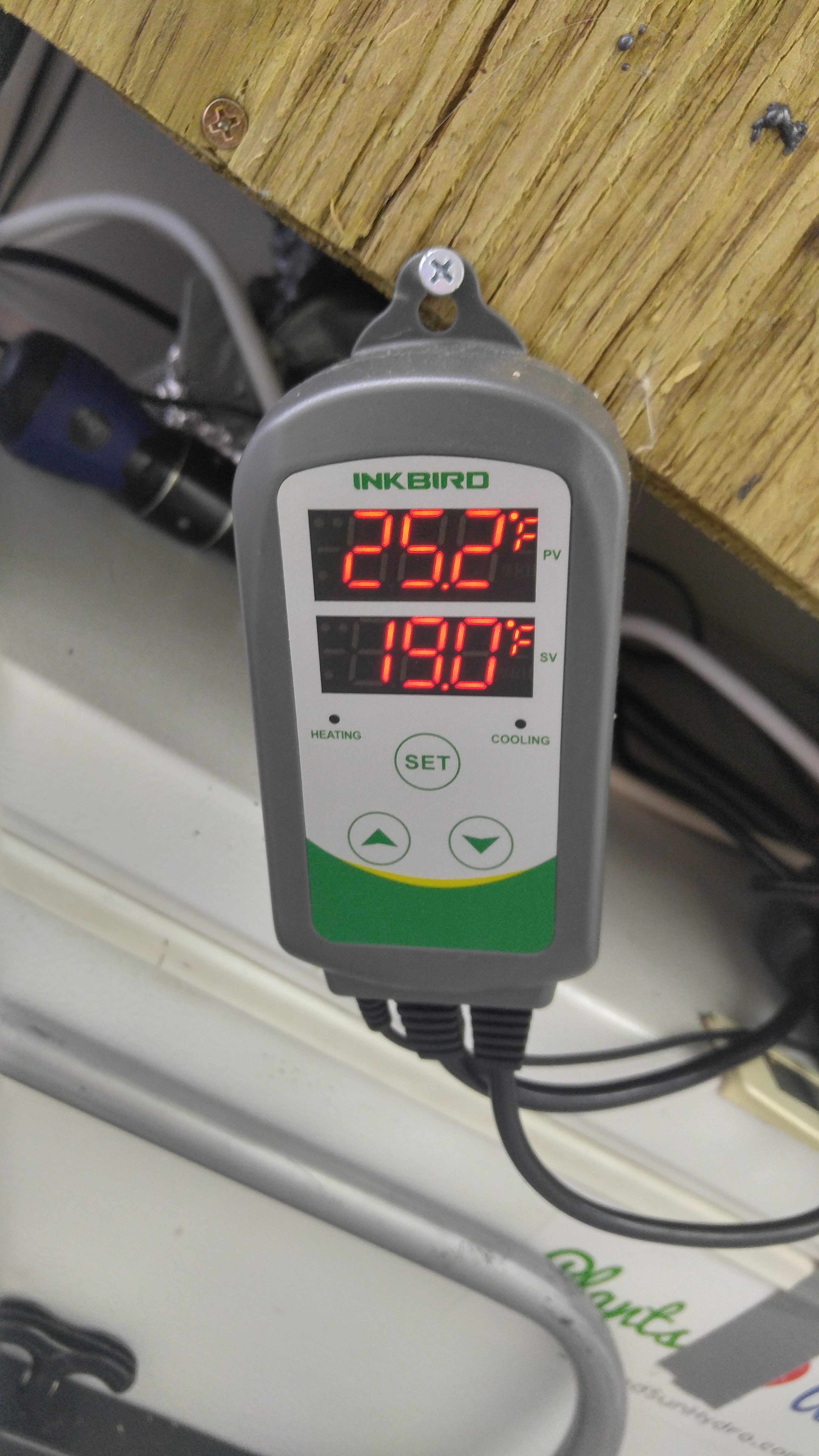
- Inkbird ITC-310T Temp Controller (for grow box temp control) – Could Also Use Something Like a Sentinel DEC-4 As Long As Sensor Can Be Kept Completely Dry
- Inkbird ITC-308 Digital Temp Controller (for Water Reservoir temp control)
- Apollo Horticulture 6″ 440CFM Adjustable Speed Inline Duct Fan
- HydroInnovations 6″ Ice Box Heat Exchanger
- 1,000 GPH ActiveAqua Water Pump
- 400 GPH ActiveAqua Water Pump
- Frigidaire 5,000 BTU Window AC Unit (NO Digital Temp Control) – Lowes is much cheaper than Amazon : see here on Lowes
- 12′ 1⁄2” Flexible Tubing (Lowes)
- 1⁄2” Thick Insulation Wrap for 1⁄2” Tubing (Lowes)
- 10 Gallon Insulated Chest Cooler (Lowes or WalMart)
- 6″ Insulated Flexible Duct or 6″ PVC Pipe (Two 90° 6″ PVC Corners Best, If You Have Room – See Notes In Guide – Lowes or Home Depot)
- (3) 6″ Duct Rings (Lowes)
- Heavy Duty Duct Tape (Lowes)
- 1 Can Waterfall Foam (Lowes)
- Jigsaw
- Razor Blade
- Wire Cutters / Hedge Shears
- Phillips & Flat Head Screwdrivers
- Drill w/Large Bit
Build a Water Chiller with Window AC Unit
The first step to build this cooling system is to take a cheap window AC unit (the cheapest one that Walmart or Lowes sells is what you want – I have the brand from Lowes) and turn it into a water chiller. DO NOT buy a more expensive AC unit that has digital temperature control. If you don’t believe the 5,000 BTUs will be enough, you can always get two and use both inside of one water reservoir for more cooling power.
Why do I do this instead of just putting the AC front directly into the grow chamber? The water reservoir allows you to store cooling power, which can allow you to get more BTUs out of your AC unit. There can actually be times when your cooling system runs and your AC does not have to run! The larger your reservoir and more AC units you use, the less the AC units will need to run. I went minimal with a 10 gallon reservoir and a single 5,000 BTU window AC.
Before you begin tearing it apart, I recommend setting the controls. Put it on the coldest setting, but have the fan on the lowest setting. Once you take off the cover, the plastic knobs easily fall off making it harder to change later (can still be done with pliers though).
You want to begin by taking apart the outside of the window AC. You’ll find screws that are holding down a metal cover around the top and sides of the AC – remove all of them but be sure to keep them handy because you will put this cover back on later. Remove that cover and also the plastic cover on the front of the AC. Behind the front cover, you’ll see a metal heat exchanger. You want that to be completely free from the rest of the AC except for the copper tubes – those must stay connected (be careful with these too, if they break then the AC is dead).

Now look for more screws around the front of the AC. There should be a couple that hold down the heat exchanger and a few more that are holding the control box on the left. Remove all of these to detach these components from their current place – removing the screws should allow them to hang free, even though they are still connected to the AC by wires and/or copper tubes.
This next part is the hardest and most important of them all…
Before you proceed, I strongly recommend putting on chemical gloves and eye goggles. I am NOT an AC technician. In fact, the AC I used was the first thing I’ve ever really taken apart, so I am not a mechanical person either. However, I do know that the copper tubes are a pressurized freon system and if you puncture those tubes the AC won’t work anymore – I would assume that the freon releasing from a pressurized system could also be dangerous, so this is why I recommend the chemical gloves and eye goggles as a precautionary measure.
In the back-left of the AC, there is a black canister and it connects to the heat exchanger with copper wires and tubes. You need to straighten out those copper wires and tubes as much as possible to extend the heat exchanger forward outside of the AC unit. This is the part you need to be careful with too, for the reasons I mentioned above.
The thick copper tubes are difficult to straighten, but you do want to avoid using tools and try to accomplish this with your hands. You don’t have to make them perfectly straight though. The point is to straighten them enough to extend the heat exchanger. You can leave the heat exchanger parallel to the AC as it began or you can rotate it out 90 degrees (I rotated mine).
The end objective here is to have the closest edge of the heat exchanger at least 2-3 inches out in front of the front edge of the AC unit. It needs to stick out enough so it can sit inside of the water reservoir cooler, and the heat exchanger needs to clear the wall thickness.

Because I bent the bottom up instead of removing it entirely, this actually gave me a front lip on the inside of the AC. I was able to nicely prop the control box against this front lip and secured it in place with some heavy duty duct tape. You can then put the top cover of the AC back in place, if you haven’t done so already – I put mine in place before cutting it. The front edges can be rather sharp after cutting, so I wrapped them in a couple layers of heavy duty duct tape.
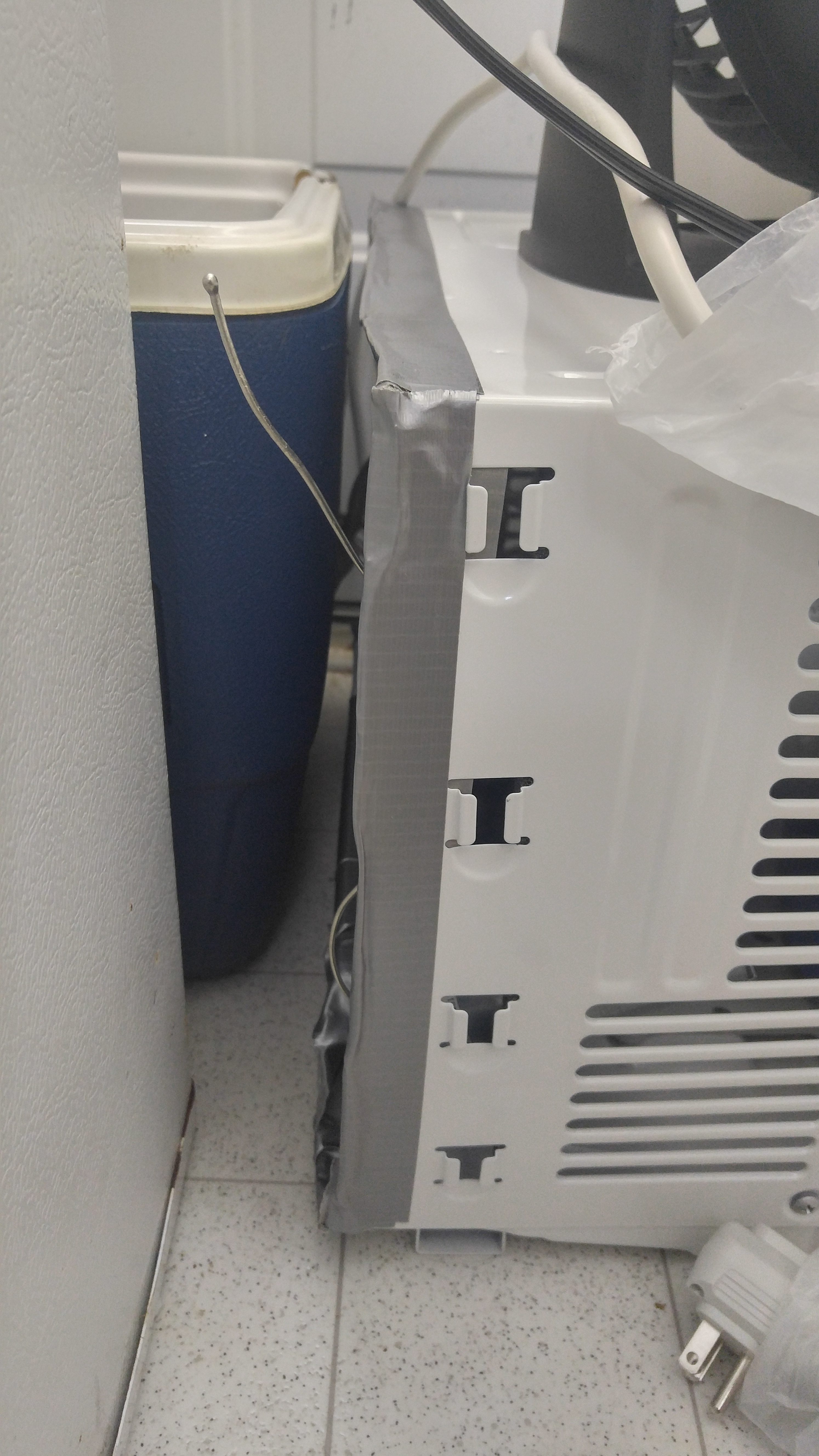
One more thing that I recommend is to install an exhaust duct onto the back of the AC unit. The AC will spit a lot of heat out the back but no water like it normally would. When air is cooled by the heat exchanger, it condensates humidity which is why an AC normally drips water out the back. However, when the heat exchanger is used to cool water instead, it will no longer leak water!
I actually found that a piece of the AC unit packaging worked good for making an exhaust duct for the AC – it’s a square piece of cardboard with a piece of styrofoam inside of it (pretty sure it is what the AC sat on top of in the box). I duct taped it to the back of the AC with the excess hanging off the top. Then, I took a small leftover sheet of pond liner tarp, duct taped a 4″ flexible duct tube into a hole in the center of it, and finally duct taped that sheet into the open space between the top of the AC and that box.

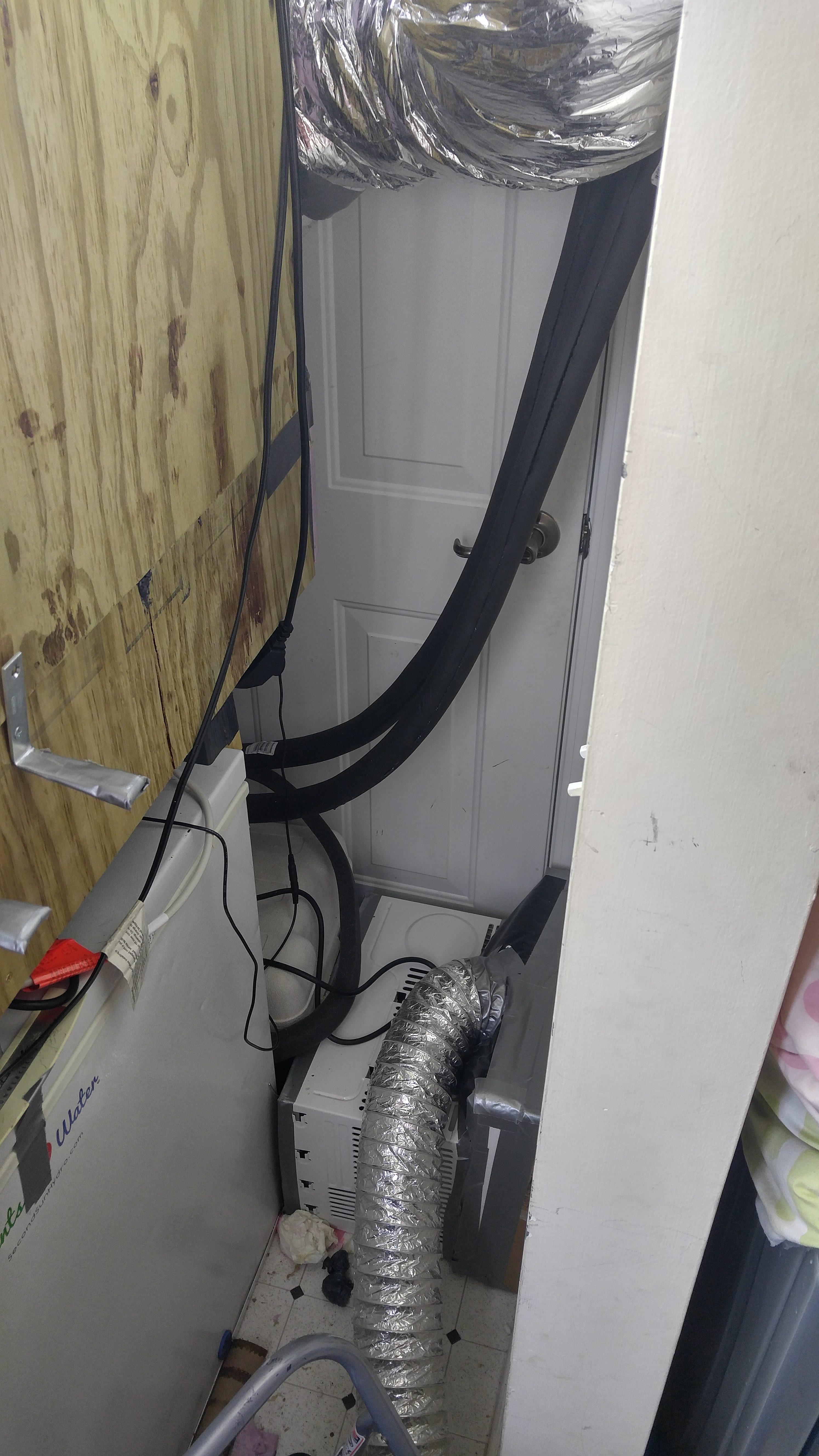
Personally I vent mine out through the dryer vent – I just got a Wye duct connector so both the dryer and my AC vent can exhaust outside. This works for me since my grow box is in the laundry room. If you are in a room in your house with a window, you can get a duct exhaust attachment that fits in windows that you can connect the exhaust to so you can vent outside. Any method of venting outside is best to remove all of that heat. However, you could run that hot air through another Ice Box connected to another water reservoir to make that water hot – the hot water could then power a heating system using a fan and separate Ice Box (if you need heating and cooling potential, you can get it from a single AC unit this way).
You could certainly build something else to catch all of the air coming out of the back of the AC to vent it elsewhere. Mine was going to be placed in the corner of a laundry room and I only had about 2″ of clearance behind the AC to work with, so this particular design worked well for my situation. With more room, I likely would’ve built that exhaust slightly different to give the back of the AC more clearance.
Prepare Water Reservoir & Install Chiller
The heat exchanger from the AC needs to go into the cold water reservoir. Before you can do that, you need to prepare the reservoir by cutting it.
I used a 40 quart / 10 gallon chest cooler. However, you could certainly go larger than that or even build your own. The larger your reservoir, the more cooling power it can store. The more insulation the cooler has, the better it can hold the cold temps.
First, try to put the empty cooler in front of your modified AC unit – get the heat exchanger to sit parallel to the cooler side. This allows you to visualize whether it will fit in the cooler as planned and also where you’ll need to make cuts. Now look at the cooler / AC from the side and note the height of the copper tubes connected to the heat exchanger – those tubes need to go through the cooler wall, so you need to figure out how low to cut to be able to do it. Mark the low point of those copper tubes where they will go through the wall.
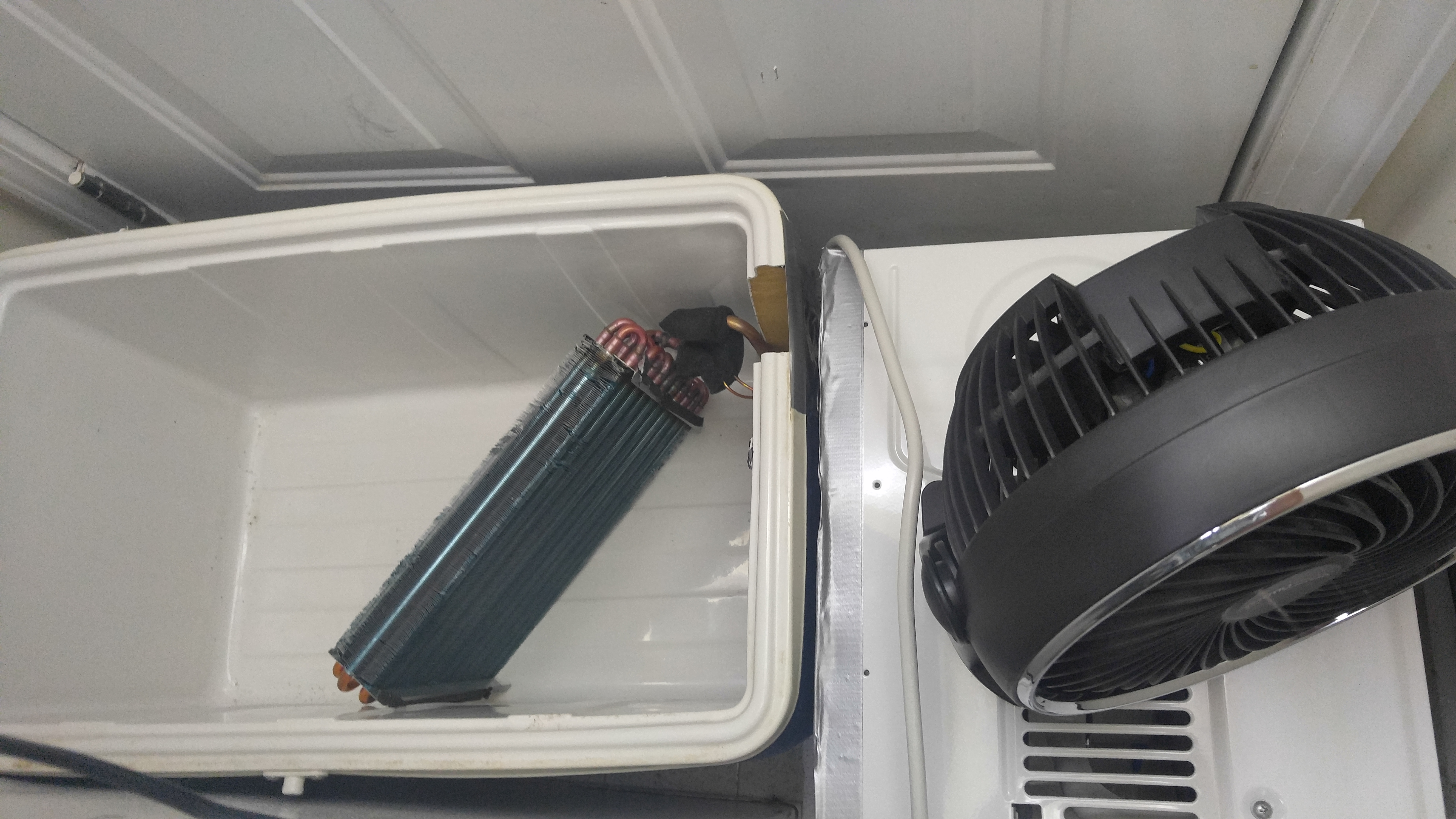
Using those marks, you can then cut down the front wall of the cooler on the left and right marks and go down until slightly below the low point, then cut across the bottom to remove that piece. I did the front wall because this is how the heat exchanger fit into my cooler and also how it would fit in the space I had for it in my laundry room. However, you could certainly cut a side wall instead if that will work better for your placement.
You also need to make a few cuts in the lid. I made 2 circular holes in the lid that were slightly larger than 1/2″ in diameter. I also cut a rectangular hole about 1.5″ x 1″ – it needs to be large enough for a few cords and also so a wall plug can pass through it. You could use a jigsaw for all of these cuts, but I had a big drill bit that I used for the circular holes.
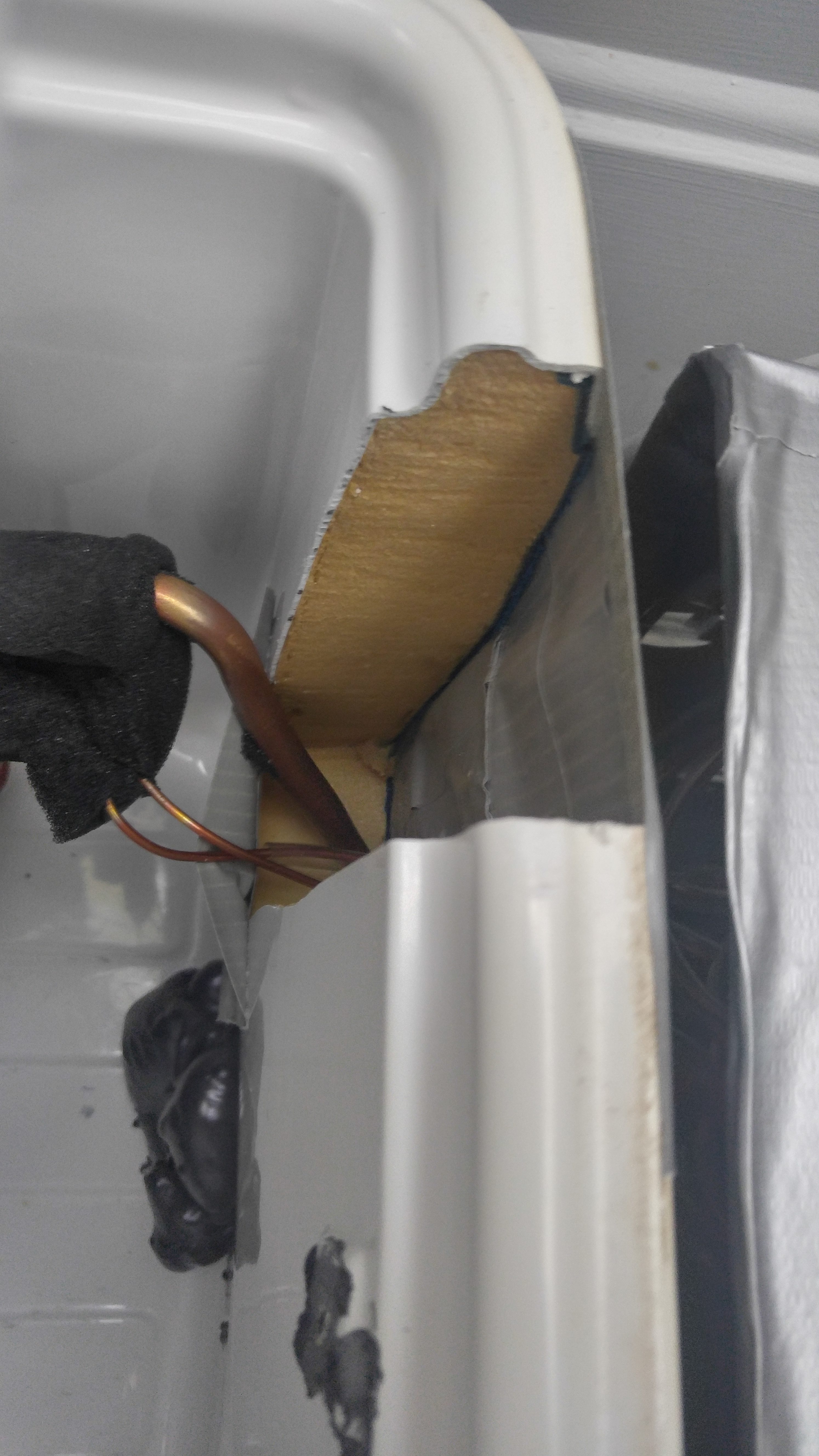
Now all you have to do is seal that wall back up. I did this using duct tape and waterfall foam. I basically recreate the wall edges with duct tape and then fill the inside with waterfall foam. However, this really needs to be done slowly from the bottom up.
I started by putting tape below the copper tubes to ensure that area got completely sealed – do this on the inside and outside of the cooler. Then you want to use waterfall foam to let it fill up the area under the copper tubes and between the tape walls.
You can want to continue to repeat this process a number of times – tape the walls a couple inches, spray foam and wait for it to dry. This will give you the most stable and solid wall.
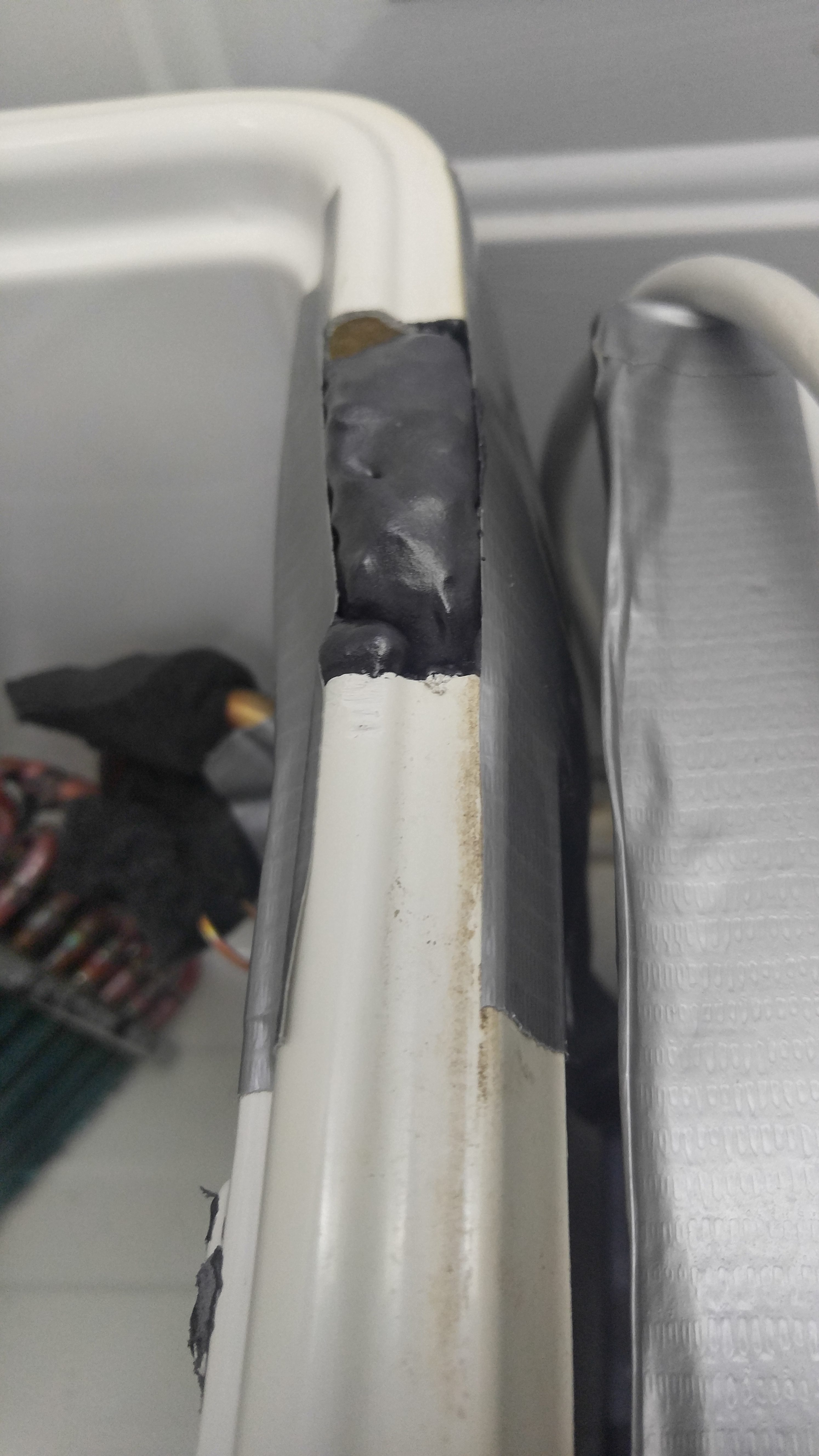
At the top of the wall after all foam has dried solid, you can trim it down to match the tops of the cooler walls so the lid will fit back on properly.
Personally, I wanted to be really sure that I wouldn’t have any leaks, so I didn’t remove the duct tape after the foam was entirely dry (which takes 24 hours to 100% cure). I also painted a very thin layer of foam on the inside wall to completely cover the duct tape – this was done to prevent leaks but also done to ensure that the water didn’t make the inside wall tape come off over time.
Fill Reservoir & Add Electronics

Now it is time to finish off the chilled water reservoir. It’s easiest to put in your pumps in first and then add the fluid, but it can really be done either way. For the electronics, you have a temperature sensor and two water pumps.
First put the two pumps in the cooler and run the power cords out the rectangular hole. One pump, the weaker pump around 400 GPH, will recirculate water inside of the cooler and push it across the heat exchanger from the AC unit. I have that pump suction cupped to one of the walls near the heat exchanger.
The second pump should also be located near the heat exchanger – the suction side of the pump should be closest. This simply ensures that the pump will pull some of the coolest water possible from the reservoir. If possible, locate this pump on the other side of the heat exchanger from the first pump.
The first pump doesn’t need a tube attached to it, but the second pump does. Figure out how far it is from the top of your water reservoir to where you will have your Ice Box and inline duct fan (could be on the side of the grow box or on a wall next to it). For mine, it was going to located on a wall very close to the grow box but about 5 feet in the air. You simply need two pieces of 1/2″ tubing that will be long enough to go from the Ice Box down to the water reservoir, although one of those pieces will need to be about 6″ – 12″ longer.
The longer piece of tubing gets attached to the second pump, which is the higher GPH pump (mine is about 900 GPH). Thread it through one of the circular holes in the cooler lid. Take the second piece of tube and thread it down through the top of the second circular hole in the lid – you just need about 3″ of that tube coming out of the bottom of the lid and the rest should be up top.
The last electronic needed is the temperature sensor for the temperature controller. You just drop the sensor through the rectangular hole in the lid top – thread enough into it so that you can still open the cooler top with the sensor still down inside of the cooler.
Now you can add your reservoir liquid. Personally, I used RV antifreeze to avoid potential freezing issues since I was going to use cold temps. I use temps between 37°F and 44°F now, but I tested it with temps as low as 15°F (my exact setup could’ve gone lower but it was way too much cooling power for my small growing area).
RV antifreeze is basically 30% propylene glycol mixed with 70% water, and you can find it at Wal-Mart for roughly $2.50 per gallon. Propylene glycol is considered food safe, while other commonly used antifreeze liquids like ethylene glycol (often in car antifreeze) are poisonous if ingested. Pure propylene glycol remains a liquid down to about -74°F, but it is very expensive to buy it this way. Mixed 30% with 70% water as RV antifreeze, it can handle -50°F and still remain a liquid, although it can start getting some ice flakes around 10°F.
You could technically use pure water, but this is only advisable if your target temps will be well above the freezing level.
Both of the 1/2″ tubes coming out of the cooler lid will get attached to the Ice Box. For now, you can just close up the water reservoir and lay the tubes on top.
Install Fan & Ice Box Heat Exchanger
The next step is to set up the inline duct fan and Ice Box heat exchanger. The placement of these two things are important though. When humid air is pulled from the grow chamber and pushed through the cold Ice Box, it will condensate humidity. You want that condensated water to be able to roll back into the reservoir in the bottom of the grow box. That water condensate can potentially be a source of dissolved minerals depending on the placement of these items and the materials used for your ducts.
My grow box is only 2.5 feet tall with the bottom six inches being a water reservoir. This means I only have 2 feet of vertical wall that I can use for ducts. Unfortunately, this didn’t really leave me enough room to attach this equipment in the most ideal way.
The best way to set this up, if possible, is to have a 90 degree 6″ PVC corner pipe coming out of the top of a wall of the grow box. That pipe will then connect to the 6″ inline duct fan, which then connects to the 6″ Ice Box. Finally, a second 90 degree PVC corner is at the bottom to connect it back to the grow box. If this can all be positioned vertical with the fan above the Ice Box, all water condensate will simply run out the bottom PVC pipe and back into the water reservoir in the grow box. For my setup, I didn’t have the vertical space to do it this way.
Since I didn’t have the vertical space on the wall of the grow chamber, I decided to put these things on the wall of my house next to the grow chamber. The inline fan I’m using has a wall mount attached, so this was the obvious starting place. However, it can be a good idea to go ahead and attach the Ice Box to the fan before you mount the fan on the wall.
This fan and Ice Box setup (especially once the ducts are added) is fairly heavy. I was able to find a horizontal stud in a wall near my grow box to mount the fan. However, if this had not been available, I was considering installing a 2×4 onto the wall of my grow box at the right height to use to mount the fan. No matter where you decide to mount it, just be sure it is going to support the weight (you don’t want to just drive those fan mount screws into drywall unless there is a stud behind it).
The key thing to remember before you mount the fan is that you need the bottom of the Ice Box to be high enough so that gravity will drain that water condensate back into the grow box water reservoir through the bottom duct that you’ll connect to it next.
Also, on one of the sides of the Ice Box, there will be a small circular hole. That is actually a water drain hole that could be used if the Ice Box is mounted horizontally instead of vertically (the hole would point down and a small tube attached to it would drain water somewhere). However, since I mount mine vertically and drain water through the ducts, I sealed up this drain hole with a piece of duct tape. Even if you mount the Ice Box horizontally and use this drain hole for it’s intended purposes, you will still end up with water in your ducts so this is definitely not a way to avoid other potential issues that I talk about below.
Connecting Air Ducts
As I mentioned before, if it is possible to use two 90 degree PVC corners to connect the fan / ice box to the grow box, I would recommend this approach.
If you cannot use the 90 degree corners because everything will simply not fit, the second best choice would be to use a series of PVC pipes to attach both sides. However, you will need to make sure that water condensate will not get stuck in those pipes – it should be a clear downhill travel back to the box.
A third option, which is actually what I am currently using (but I don’t recommend), is to use insulated flexible ducts. These are pretty affordable and the insulation around the 6″ duct works great. However, the problem is the water condensate – it gets stuck inside of the flexible duct very easily. When water sits inside of these ducts, it slow causes problems because it degrades the materials used in the ducts. Specifically, it seems to be the metal wire coil that wraps through the entire duct. That metal coil is able to rust when water sits on it. When enough water builds up in the duct, some of it ends up finding it’s way back to your water reservoir and polluting it.
I am still using the flexible duct at the moment of this writing, but I am planning to change to all PVC pipes in the near future. However, this will be a bit costly and complicated since my fan and ice box sit a couple feet away from my grow chamber. This is why my #1 recommended approach is the corner PVC pipes and installing everything directly on the grow chamber wall vertically – it’s cheapest, easiest and will work the best.
After my grow chamber was running for about a month, I noticed water pooled up inside of one of my flexible ducts. I drained out some of this water into a cup so I could test it – it was about 140 ppm! I discovered this because my water reservoir in the grow box had slowly crept up to 40 ppm.
I ended up trying to fix the flat areas as much as I could and did a complete water change in my reservoir. It fixed most of the problem, but the water reservoir has still crept up about 10-15ppm over a month. This simply means that I will have to continue with semi-regular water reservoir changes until I switch to PVC pipes, which is the big reason I recommend avoiding the flexible ducts from the beginning. With PVC pipes, the materials shouldn’t be leeching dissolved solids back into the water, even if some sits in them.
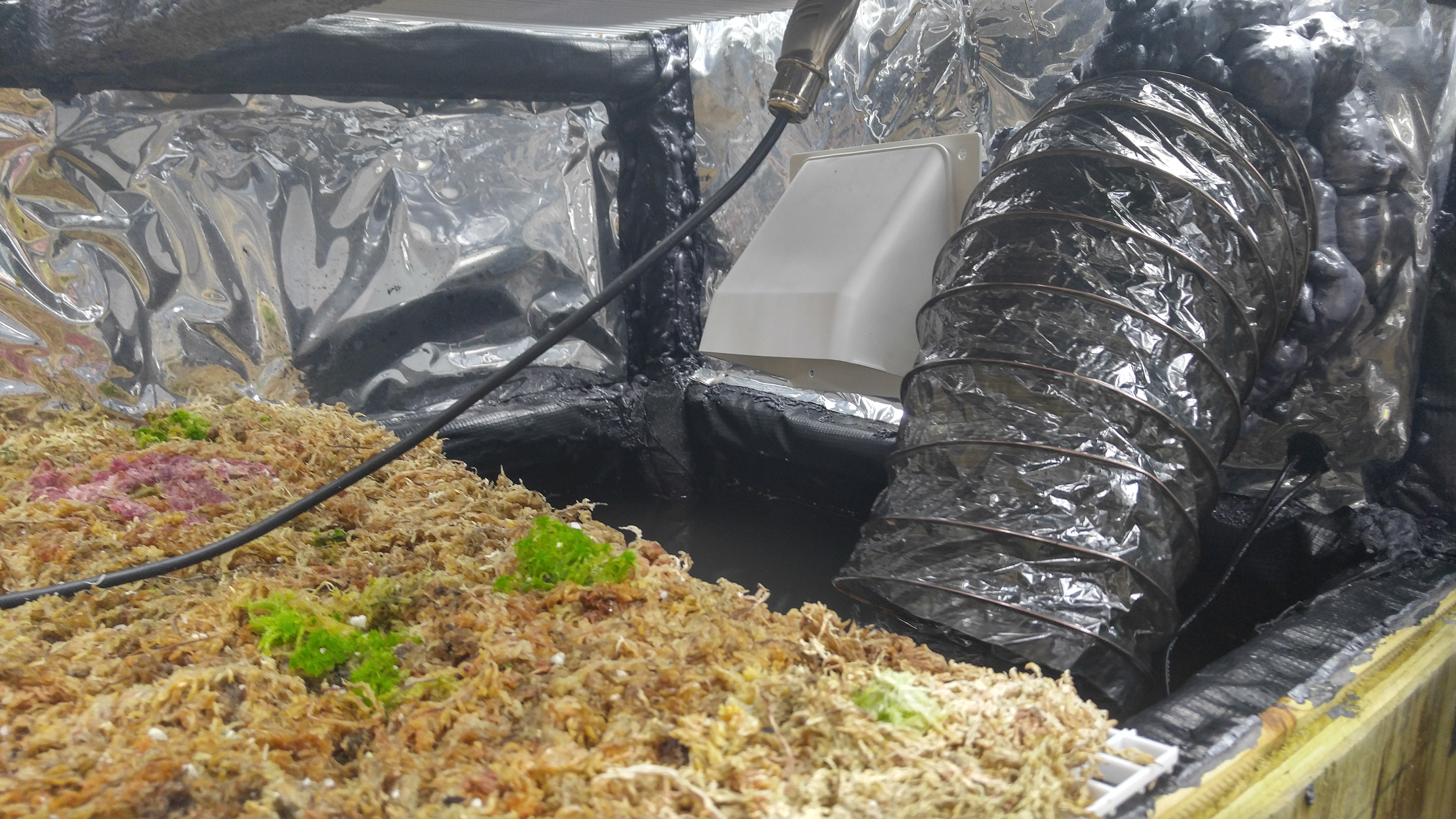
Whatever you end up using for your ducts, the idea is still the same. You want a duct coming out of the top of a wall of your chamber and connecting to the top of the fan – this should be where the fan is pulling air from, so it will suck the warmest air out of your grow box. Then you want another duct coming out of the bottom of the Ice Box and connecting to the bottom of the grow chamber wall. This can all be done on the same wall of the grow chamber (I’ve put it on the right wall of my chamber).
To install these ducts on the grow chamber wall, I just cut a circular hole that was slightly larger than 6″. The top duct, I wanted this to barely come inside of the grow box enough to be able to make a seal. However, for the bottom duct, I have it coming inside of the grow box about 6″-12″ (just the inner duct part and not the insulation though). This extra bit inside of the box allows me to direct the cold air down towards the water reservoir where the ultrasonic humidifiers are running – it simply ensures that the air gets humidified before it gets to the plants.
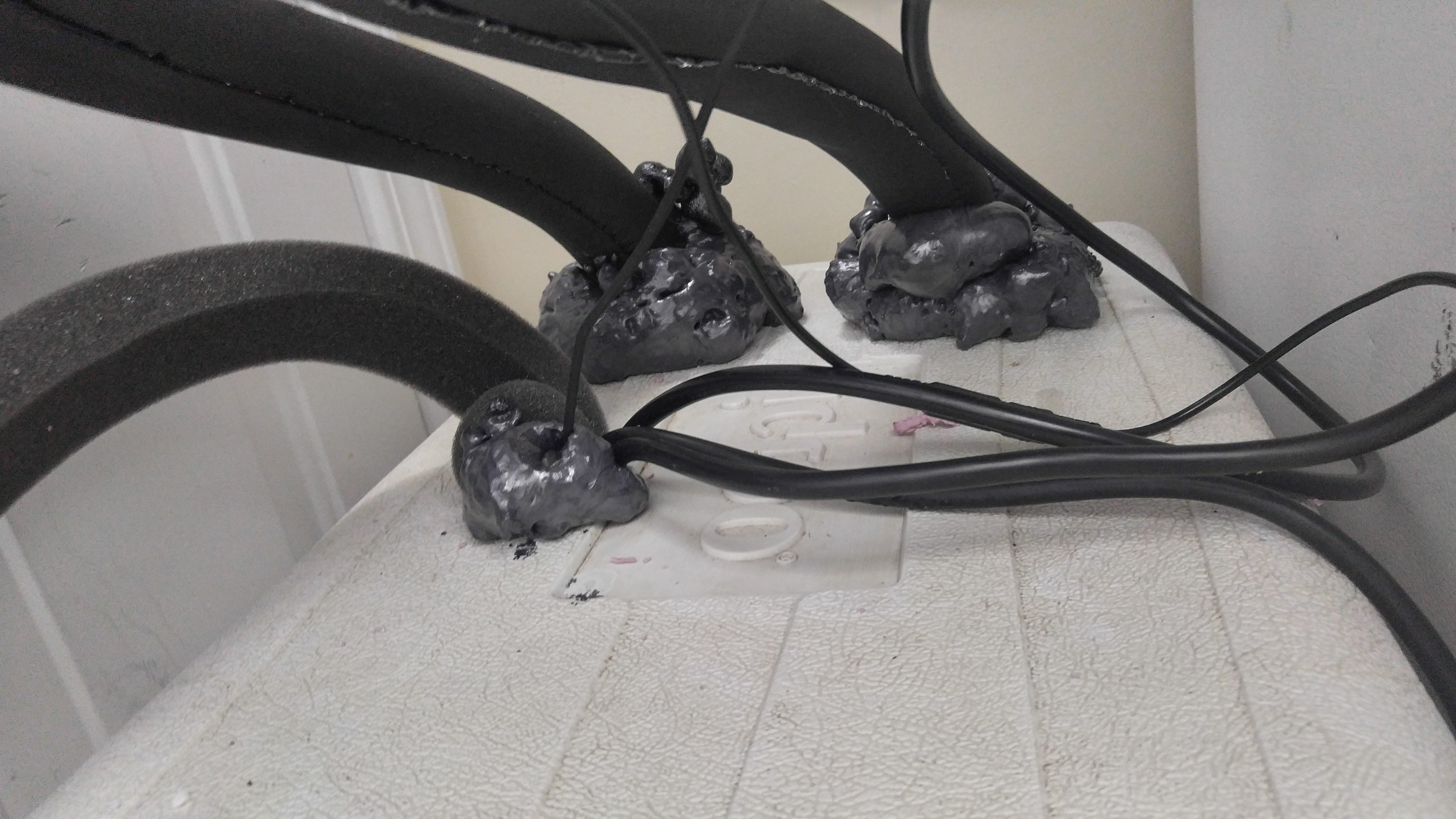
To seal the ducts to the grow chamber wall, I used waterfall foam. A thin line of it on the inside and outside of the wall around the duct is plenty to hold it in place and create an airtight and watertight seal.
Connect & Seal Cold Water Lines
The two tubes that are coming out of the top of the cold water reservoir lid need to be connected to the Ice Box. I highly recommend using 1/2″ tube clamps to connect those tubes onto the Ice Box to be sure that your water doesn’t end up pushing them off over time (especially if you’re going to use RV antifreeze too). The Ice Box came with two of these clamps.
With those two tubes connected, if gives your coolant a way to travel from the pump in the reservoir up to the Ice Box and back down into the cooler again.
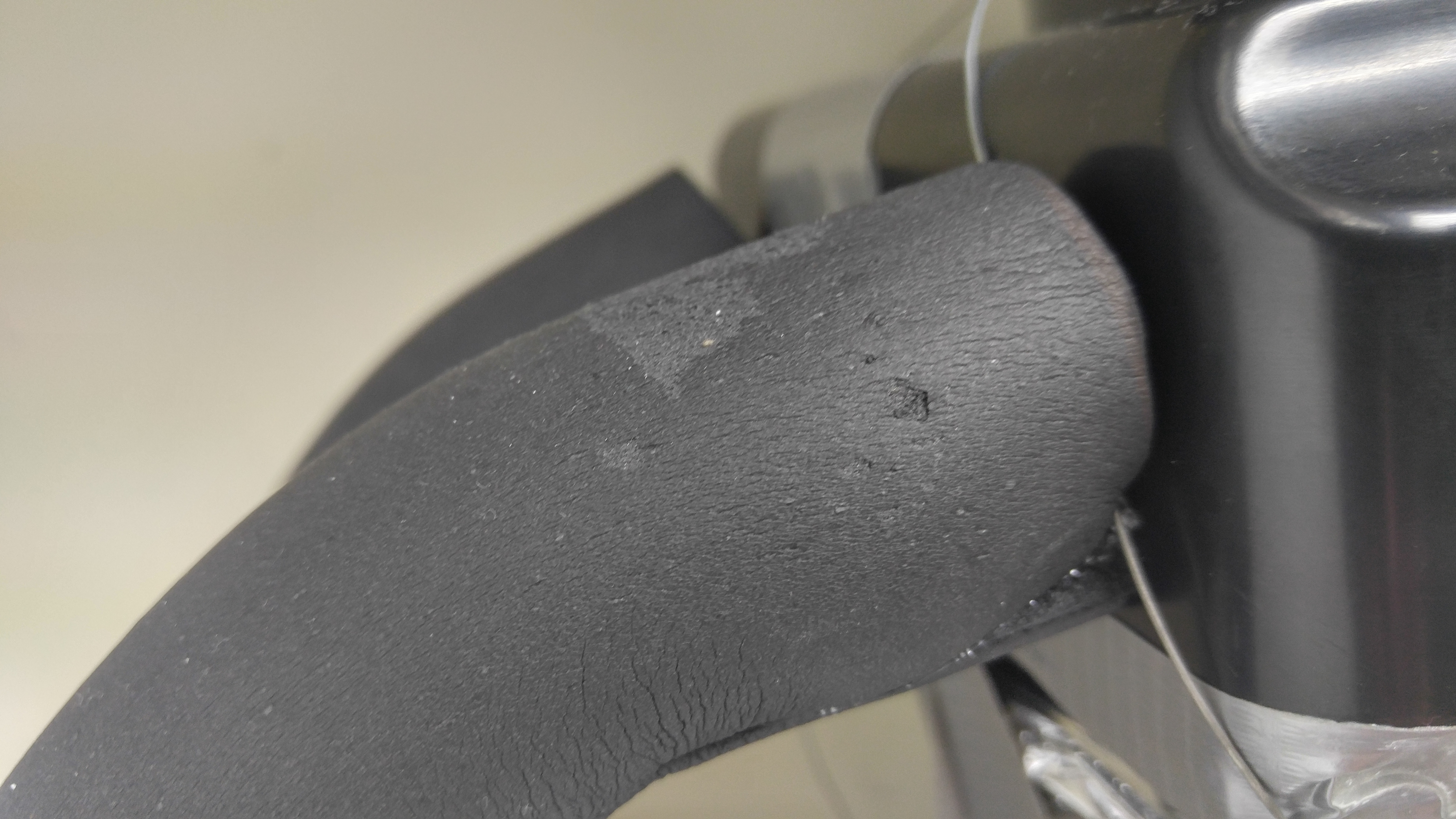
Start by wrapping the insulation around the tube beginning at the top. Try to get the insulation as close to the edge of the Ice Box as possible. You can even tape it in place temporarily to hold it there. Wrap the entire length of the tube.
Once the tube is wrapped, start peeling off the adhesive backing beginning at the top. Peel it off both sides and then squeeze the sides together to make them stick. Repeat this a few inches at a time to wrap the entire tube and repeat the same process on the second tube.
You should end up with a wrapped tube that is covered all the way from the Ice Box edge down to the edge of the cooler. You really don’t want ANY exposed tube.
Where these tubes attach to the cooler lid, use some waterfall foam to seal them in place. I put some around the actual 1/2″ tube to seal it in place and then lowered the insulation wrap on top of it and finally foamed around the insulation wrap to seal it to the top of the cooler lid too.
I just did my foam sealing on the top of the cooler lid and not on the underside. While I was at it, I found it to be a good time to go ahead and seal the rectangular hole that has the power cords and temperature sensor – just make sure the sensor cord is in the cooler as much as you can stretch it and also make sure the water pump power cords are out of the cooler as much as they can be without making them move (you can’t make these cords too tight or it drags the pumps).
Final Connections for Water-Cooled AC
At this point, your homemade water-cooled air conditioner is basically complete! All you need to do now is make some final connections to get it working.
First, the lower power pump in the coolant needs to be plugged in to run all the time. I ended up using an extension cord for this one to connect it to another power strip that runs fans 24/7.
The more powerful pump is the one that will recirculate the cold antifreeze through the Ice Box. That pump I have plugged into it’s own power strip, but don’t plug that power strip in yet. I have also plugged two ultrasonic humidifiers into that same power strip – these humidifiers are in the water reservoir inside of the grow chamber (at least one is right at the duct outlet so it is the first thing that the cooled air comes in contact with).
The inline duct fan is also plugged into this power strip. Personally, I have the speed dial turned very low but not quite as low as it will go. Use a lower fan speed to get the chamber to cool more gradually. At high speed, it can drop my chamber 25°F in a mere 30 minutes but I prefer this process to take about 2-3 hours. This holds the Nepenthes in the box around 50°F for about 7 hours of the night until the lights come on.
That surge protector strip with a pump, two humidifiers and a fan plugged into it will need to be plugged into you environment controller that has a sensor in your growing area. I’m using the Inkbird ITC-310T that lets me control separate day and night temperatures – the power strip is plugged into the cooling socket. However, you could use any temperature controller as long as it can have a different temp for days and nights.
With that connected to the Inkbird ITC-310T, it automatically turns on cooling whenever the temperature is above the set limits. When the lights are on, I limit my highland Neps to 77°F, so if the temp goes above that level it will cool the box down to 75°F (the 310T is set at 75° with a 2° range). When the lights are off, the night temp setting kicks in, which is set at 50°F. Since it will always be in the 70s when the lights go off, the cooling automatically turns on at that time. It then cools everything down to 50°F before turning off. Then when temps creep back above 52°F it will cool the box down to 50 again.
The actual temp you keep your reservoir at will depend on the size of your grow chamber, your total cooling BTUs of your AC(s) and the size of the reservoir. Try a temp that is about 13-15°F below the lowest temp you want your growing area to reach. If needed, you can adjust up or down from there to dial in the cooling system. You want it set to the highest possible temperature level while still being able to cool your growing area to your desired temp in a couple hours – this will be the most energy efficient setting for your system.
My temp controller for the coolant reservoir also allows me to set a delay, which I have at two minutes (prevents the AC compressor for cycling on too often). It also allows me to set a cooling temp range, which I have at 7°F. That range is what controls when the AC will turn on.
My target grow area temp at night is 50°F. I have my cold water / antifreeze reservoir set at 37°F with a range of 7°F, so the AC will turn on to cool down the reservoir when the temp in it tops 44°F.
After a couple of months of use, this cooling system has held up very nicely. There has not been any degrading of cooling power and all of the equipment still works great without showing any current signs of wear except for the insulated flexible duct issue that I mentioned earlier.
There really isn’t much to do with this system as far as maintenance goes either. As long as the AC, fan and water pumps keep working, the system will basically run itself. Beyond just checking on it every now and again to ensure the equipment still works properly, just make sure that the cold water reservoir level isn’t going down. With a sealed system, you shouldn’t be losing any of it, but it can still be a good idea to check it once every couple of months (be careful lifting the cooler lid though – make sure the turn your 24/7 pump off first).
Any of the electronics in this setup that could potentially break down would be pretty easy to replace. Another AC unit could be quickly picked up at Lowes / Wal-Mart if the existing one stopped working. In a pinch, new pumps could also be picked up at a local Lowes, but these are a lot cheaper if purchased on Amazon.
» Chest Freezer Air Conditioner
This second DIY AC method that I’m going to teach you is a possible method that you can use that is often very cheap. However, please note that this cooling system has it’s limitations – namely that it isn’t very powerful and it will require regular draining of water to keep it working efficiently.
With that said though, if you are growing your plants in a chamber in an unheated basement, this is a more practical solution because there will be naturally cooler temps in that environment. It’s also possible to use this if you do not need to drop temps down to 50°F like I needed.
Try to measure the area of the inside of your growing area and also your chest freezer. The results I achieved were done with a freezer that has 40% of the area of my grow chamber (the chamber is 20 cubic feet, so the freezer is 8 cubic feet). If you have a lower ratio of freezer to growing area, you’ll likely get worse cooling results than I achieved unless you have a heavily insulated chamber.
Another factor that will drastically affect the effectiveness of this cooling system is how airtight and insulated is your growing area. For example, my highland Nepenthes seedling chamber was using a chest freezer that had about 40% of the area as the chamber. The chamber was mostly sealed and had about 1/2″ of insulation board around most of it. This chest freezer method was able to drop temps down from 77°F down to about 57°F – 60°F for most of the night. However, if I simply threw a few thick blankets over the grow chamber each night and removed them each morning, the same cooling system was able to get down to 50°F – 52°F. This goes to show you that the insulation can make a big difference, so if you will build a very sealed and insulated chamber better than what I’ve done it would be possible to get a chest freezer AC to work pretty decent (minus the regular maintenance still).
I’ve seen some people use a chest freezer as their antifreeze reservoir and chiller, but even in a basement environment it doesn’t seem to be powerful enough to maintain even 55°F temps for about 6 hours (just based on what I’ve seen others do). If you want to go water cooling, use the method I detailed above.
The main problem with a chest freezer as an air conditioner is that the extreme cold of the freezer gets quickly overrun by warm air that is recirculated through it. It can cool air down to a certain point fairly quickly, but it can actually have problems maintaining that low temp for any prolonged period of time.
With growing Nepenthes and other plants needing a nighttime temperature drop, you have another option though. As long as you don’t need to use the freezer for cooling power during the day, you can use that time to store cooling power to be used at night.
To store cooling power with a chest freezer, you simply use jugs of water. You want the jugs of water to be about 75% full with some of the extra air squeezed out – this gives the jug room to expand when it freezes. With these water jugs in the chest freezer, they are frozen during the day and then that stored energy is released at night by recirculating grow chamber air through the freezer. With enough jugs in the freezer, it can typically maintain cool temperatures throughout a 10 hour night with the remaining 14 hours of each day being used to freeze the jugs again.
Regular, Ongoing Maintenance
The biggest downside to this method beyond the low cooling power is condensation. When warmer, humid air is passed through the cold freezer, the air condensates some of that humidity inside of the freezer. Over time, this water will begin to add up. Ice crystals will form over everything in the freezer, including the walls. This simply decreases the cooling power of the freezer gradually.
The only way to combat this problem is with regular maintenance in the form of emptying water from the chest freezer. They generally have some kind of a drain on the bottom that can be used. This regular maintenance is really the main reason why I don’t use this type of cooling system anymore.
In some situations, you may be able to leave that drain open all the time and simply have it connected to a tube that allows the water to automatically drain as it accumulates. However, to do this you would need to have somewhere downhill for that tube to go that could continually drain water without causing other issues.
I’ve done this chest freezer setup in a basement before and simply allowed the water to drain out onto the floor where a powerful fan was running to continually dry out that area. However, that wasn’t the most ideal setup.
If you will be manually draining the freezer of water, the best time to do it is likely going to be right before the lights turn on for the plants or sometime during the night. When the lights turn on, the cooling system will stop running – that is when the freezer is able to truly start cooling again (at least to the point where it can turn water into ice). Basically, you just want to drain the freezer when the contents inside are most likely to be water so all of that condensate can drain away instead of pooling in the bottom.
Freezer Placement
Chest freezers are pretty large, so when you decide to use one as a cooling system you will have to figure out where it will be located in reference to your plant chamber. Before you decide on a final location for it, you need to consider three things: duct length, duct location and heat.
Most chest freezers open on the top with a hinged lid, so it is easy to tell that there are no electronics or other equipment inside of that lid. That means it is safe to cut through the lid of the freezer without damaging it’s cooling ability. The sides typically have coils running through them, so if you were to cut a side wall it would ruin the freezer. For this reason, the duct location typically needs to be on the top of the freezer.
Where you locate the freezer in relation to the grow chamber will drastically affect the length of ducting you’ll need and the amount of ambient heat around your grow box. When the freezer is far away from your grow box or potentially even in another room, you’ll have to use a lot of ducting and possibly higher powered fans to move air through them. You may also end up losing some of the cool air in the ducts to the outside if the ducts are not well insulated.
When the compressor in the freezer is running, the outside sides of it will get hot (these are the coils I was talking about earlier). In a fairly small room, this can easily raise ambient temps 5-10°F unless you provide good ventilation in that room to remove a lot of that warm air.
With all of that said, you can have the freezer directly under or next to your grow box. This gives the shortest duct length, but you do have to deal with the warmer conditions. If you own your home, you would consider putting the freezer in the garage and the grow box in a neighboring room – simply cut holes through the wall for the ducts to pass through. You could technically remove all of the freezer heat this way and still have very short ducts if the box was directly on the other side of the wall.
I recently ran this chest freezer setup with my grow box placed on top of it. It was very sturdy support for the box. I simply had a large box fan keeping the outside of the freezer as cool as possible and also recirculating that air out of the room.
Once you know where the freezer will be located, go ahead and plug it in so it can start getting cold. Make sure it is turned to it’s coldest settings. You can then begin on the actual work to create your chest freezer air conditioner.
Cutting Duct Holes
The most difficult part with this entire setup is cutting through the top of the freezer. Your goal is to create two circular holes in the top that are slightly wider than your ducts.
The lid of the freezer generally has three layers – metal, then insulation and finally some kind of rubber and/or plastic. If you open the freezer lid, you can see the rubber / plastic lining on the underside and the metal side is on top of the lid.
The metal is obviously the tough part to get through. I don’t exactly have tons of tools for something like this, so it is possible I simply didn’t have the best equipment.
First I measured the holes and marked them on the top of the freezer lid. You want some space between these holes but also try not to put them right up against the sides because you also want a bit of space between the walls and the ducts.
Then I used a large drill bit in the center of each marked circle. The goal here is to drill a hole through that metal lid, and you want the hole to be a bit wider than the blade you have for the jigsaw.
With the hole made in the center, you can then get the jigsaw blade in there and start cutting. This process was actually rather loud and slow, and it caused a ton of vibrations through the jigsaw to make my hands go numb.
I ended up switching to a pair of hedge clippers. I found these were able to clip through that metal with ease, so I simply used these to snip around the outside of the circle to create those holes in the top of the freezer.
Once the metal piece is gone, you’ll see the insulation below. I moved that insulation away to clear the circular area – this was fairly easy to do by simply pushing the insulation out to the sides around the edge of the circle.
When you have the plastic lining completely exposed, you just need to cut a matching circular hole in it for each duct. I found this easiest to do with a razor blade.
Inside The Chest Freezer
Before you start connecting ducts to your freezer, you’ll want to prepare the inside of it first. The main goal here is to fill up as much of the freezer as possible with jugs of water, although you do want to leave some room between the jugs for air and for some duct work.
Remember that water expands when it freezes. For this reason, you don’t want to use completely full water jugs. Fill them up about 75%. Before you put on the lid, squeeze the empty area at the top of the jug to remove some of the air in it and then cap it (with the jug still compressed a bit towards the top). This simply helps to ensure that the water jugs won’t split when the freeze.
If you have a fairly deep freezer, you may need to shoot to have multiple layers of water jugs in it. The easiest way to accomplish this and still have stability so the jugs don’t fall over and spill is to put a hard surface between each level of water jugs. For example, you could use something like a piece of wood to put on top of a layer of jugs, which will then create a hard, flat surface for the next layer.
The biggest thing you need to remember when placing these jugs in the freezer is that you will need to have some room left for ducts. You basically want a duct going from the holes in the top of the lid down into the freezer, but you also want these ducts to wrap around as many freezer jugs as possible. Also try to ensure that the ducts will be able to go all the way to the bottom of the freezer, but the two ducts should be separated by at least a few feet.
Depending on how many water jugs you’ll be using and how you’ll be placing them, it may be easiest to start laying ducts in the freezer as you load up the jugs instead of doing it after all of the water is in.
Recirculating Fans & Ducts
Start at the bottom of the freezer and begin to lay some flexible ducts. I initially tried using the actual metal, flexible ducts. They worked great for temperature exchange, but they proved to be fragile at low temps (they simply started coming apart at the joints and unraveling). For this reason, the cheap flexible duct tubing can be used (I did 4″ ducts for my freezer). I ended up putting something like 30 feet worth of ducting into mine.
This ducting inside of the freezer simply gives the air distance that it must travel before it can come back out of the freezer. By keeping the air in the freezer longer and running it around water jugs, it can cool down more.
Once you have the two ducts and water jugs in the freezer, you need to pull each duct up through a hole in the freezer lid. Try to get at least 6 inches of duct coming out of the top of the freezer lid.
With the ducts completely in place, use waterfall foam to seal them in place in the holes in the freezer lid. Go around the ducts on both the underside and top of the freezer lid with the waterfall foam to seal. Once this is done, close the freezer and give it some time to dry – 30 minutes or so is usually enough.
Now that the ducts are in place and dried, it is time to attach the fans. I’m using 4″ inline duct fans connected to each of the two ducts coming out of the freezer lid. You simply want to have one fan blowing air into the freezer and the other fan pulling air out. Using a 4″ duct clamp, these are pretty easy to connect.
Once the fans are connected, you just need to connect another piece of duct to each of them, which will then get connected to the grow box to create a recirculating air loop. I put these duct connections on the grow box on opposite sides to help ensure that the cold air would mix nicely. The duct that pulls air out of the grow box and pushes it into the freezer is located at the top of the grow box to ensure that it removes the hottest air. Just like with the freezer lid, I also sealed these ducts using waterfall foam.
The duct that will put cold air into the grow chamber is located near the bottom on the right wall. This puts the cold air exhaust right above my water reservoir so I can have an ultrasonic humidifier running there whenever the cooling system is active to counteract the lost humidity from condensation inside of the freezer.
Final Connections for Chest Freezer AC
The main thing left to do now is to connect your electronics.
The freezer should already be plugged in. Ideally, try to let it run for at least 12 hours and maybe even for 24 hours before it will actually be used to cool your grow chamber – this gives the water jugs adequate time to freeze. You want the freezer plugged into 24/7 so that it will turn on the compressor as needed to keep the freezer cold. During the cooling cycle, the freezer will run the entire time. However, during the day the freezer should get to rest for some period of time before the night cooling starts again.
The two inline duct fans connected to the freezer ultimately control your cooling system now. Simply plug these into a thermostat that will turn on at night to cool the grow box to your desired temperature. I also recommend having 1-2 ultrasonic humidifiers plugged into this same socket so they will run whenever the cooling system fans are running – this keeps humidity at 95%+ levels throughout the night, which is ideal for highland Nepenthes that I grow.
If you find that your freezer cooling system cannot hit the temps you want, try to insulate and seal your chamber more. You may even be able to remove some ambient heat from the room to lower temps more, especially if the freezer is in the same room.