
Highland Chamber
Build Guide Menu
I’ve created numerous growing areas for highland Nepenthes carnivorous pitcher plants over the years with varying degrees of success. However, after enough trial-and-error, I finally figured out how to build a chamber that I can maintain at the exact temperatures and humidity levels that I want to achieve. This type of indoor greenhouse allows me to create perfect conditions to grow some of the rarest, most beautiful and most sought after neps in the world like n. hamata, n. macrophylla, n. lowii, n. rajah, n. aristolochioides, n. jamban, n. jacquelineae and n. edwardsiana. It’s also great for any other cool night, high humidity loving plant like other epiphytes, orchids, heliamphora, etc.
This extensive guide will not only give you a tutorial on how to build the perfect highland Nepenthes chamber, it will also teach you about my failures and mistakes along the way too! By knowing about my mistakes, you can easily save yourself hundreds of dollars in the construction process.
This guide actually contains four parts. I’m going to walk you through the construction of the grow room itself first, and then I’m going to teach you two different cooling system methods. Finally, I’ll show you how I built my automated watering system. You can certainly try to follow this lesson exactly, but also keep in mind that this can definitely be modified in some ways too (ie, building a larger chamber than I built or just using part of my build like the watering or cooling system).
My Grow Chamber Purpose & Design Overview
The box I’m building is 2 ft. deep x 4 ft. long x 2.5 ft. tall. It’s intended to be a seedling / young plant chamber. It would be suitable for plants as large as 2′ in diameter and as much as 18-20″ tall. For small 3″ pots, you can fit about 100 plants in my growing area. For anything larger in size and/or quantity, you would want to build a larger chamber.
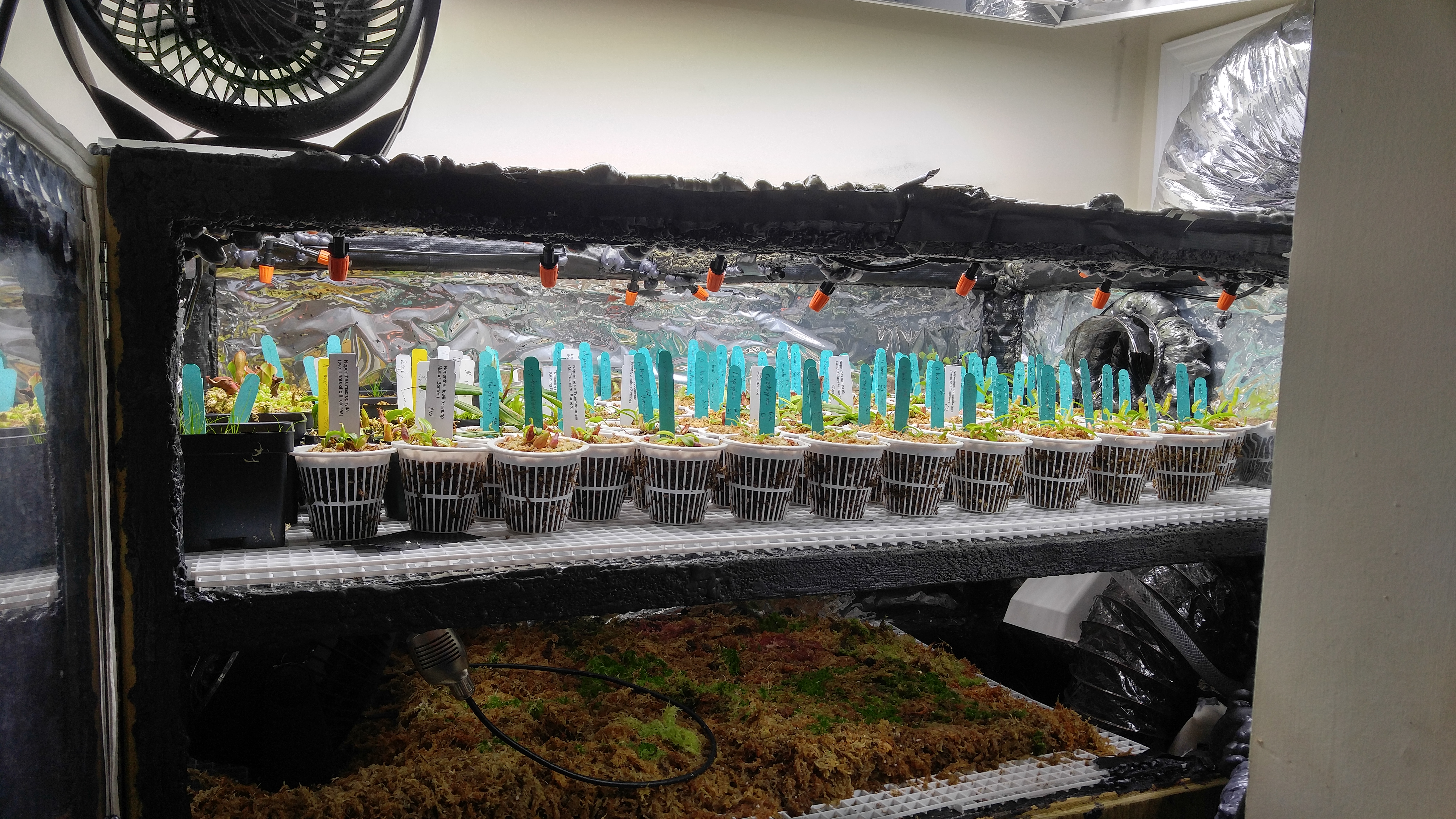
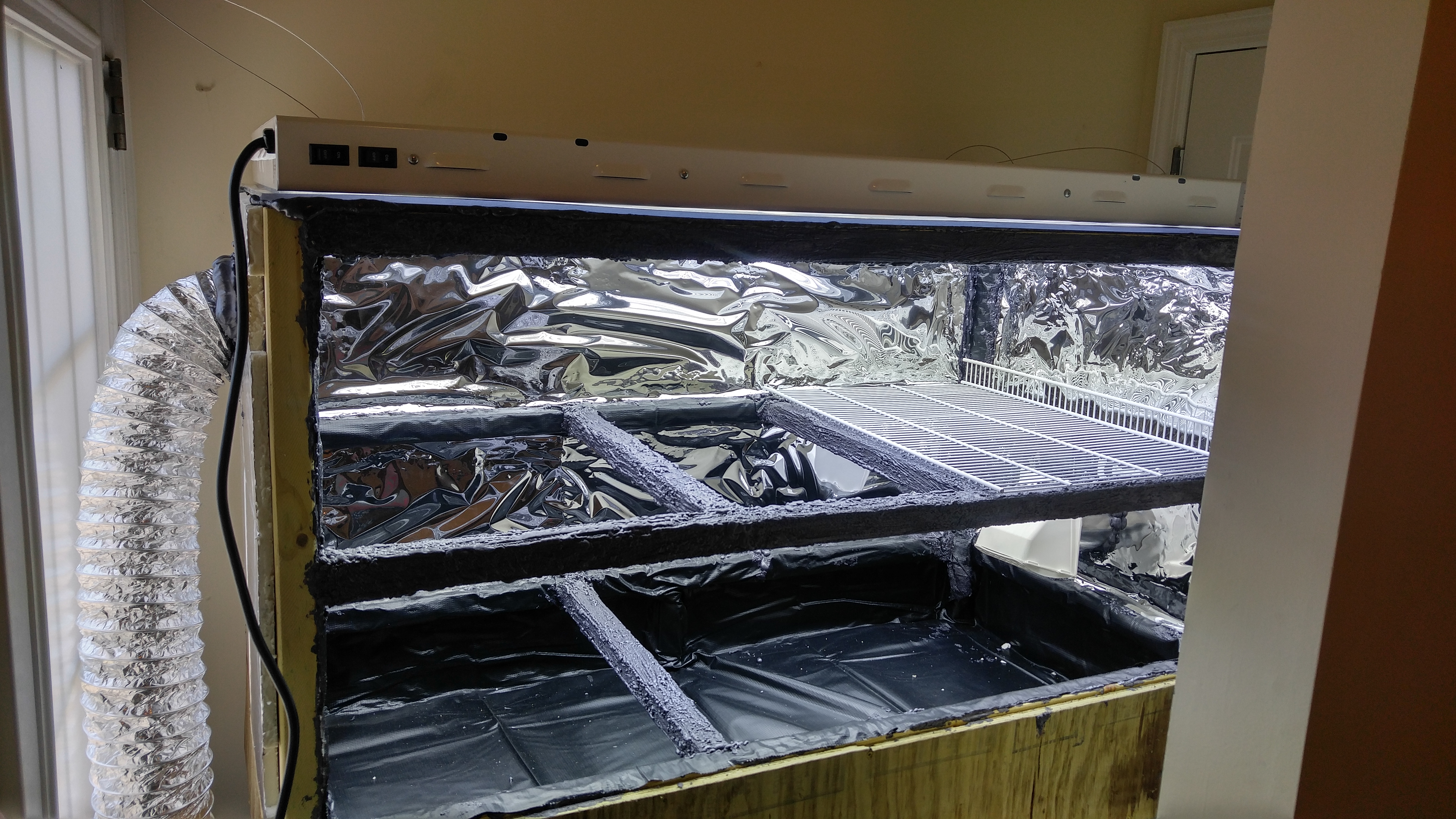
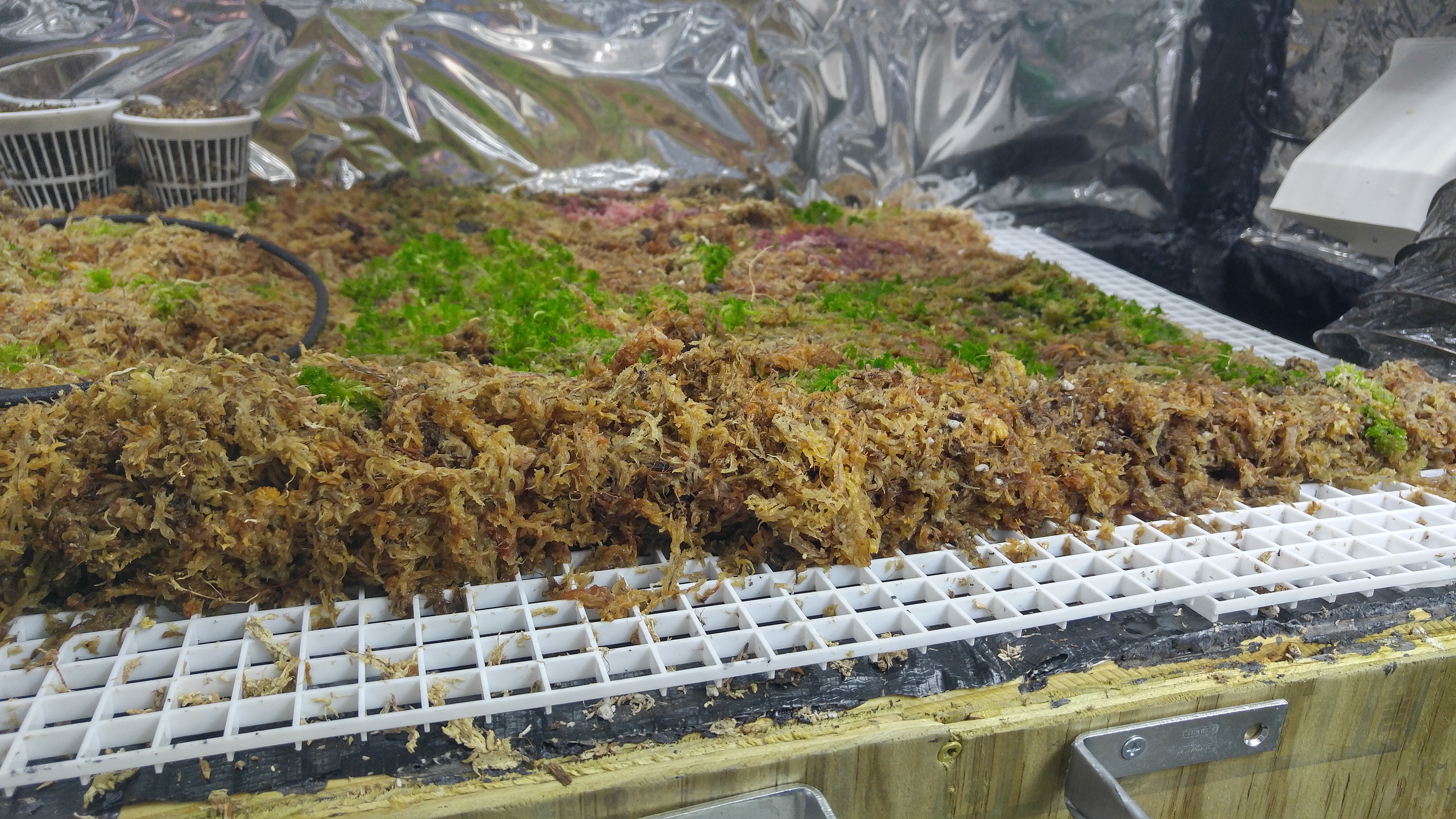
I designed this chamber to be both automated and flexible. It has three levels. The top level is a removable shelf. The second level is also a removable shelf. This allows me to start smaller plants up top. When they get too tall, I can simply take them out, remove the top shelf and put them all on the bottom shelf – this will give them about 11″ more inches to grow up. Beyond that point they would need to move to a larger chamber. Personally, I like to put a 10″ fan on the bottom shelf and cover the rest of it with live sphagnum moss.
I also mentioned a third level but didn’t explain it. The very bottom of the grow chamber is a built-in water reservoir that is about 7.5″ deep. This reservoir serves a number of purposes.
First, I have this thing inside my house so I don’t want it leaking water. The reservoir catches any run-off water from the chamber when the pitcher plants and moss get watered.
The second purposes of the reservoir is for humidity. Passively, this water will keep a high humidity level. However, when the cooling system runs the chamber will need extra humidity. This extra humidity is achieved with floating ultrasonic humidifier foggers, and they simply float around in the water and turn on as needed.
The final purpose of the reservoir is for the automated watering system. A pump sits in the water and pumps it up through tubes to the sprinklers. Excess watering and even condensation can simply fall back to the bottom, so this creates a recirculating water system. When set up right, the only care your plants will need is to fill the water reservoir when it gets low (this can take weeks, a month or even longer). By simply keeping water and power in the system, this chamber can completely care for your plants for you.
My plans outlined here would work for a bigger chamber, but do keep in mind that you would need to make some adjustments to my plans to go bigger (more lights, more fans, more foggers, more cooling power, etc). The bigger you go, the more you will spend, so go for a small design like mine if you do not need tons of growing space yet because you can always build more / larger boxes in the future – a small highland Nep can take years to outgrow this area.
How to Achieve Big Night Temp Drops
Highlanders grow at a variety of altitudes in their natural mountain habitats – some of these like slightly warmer nights (55-60°F) while the higher elevation plants appreciate night time drops to 50°F. Most of the plants I’ll be growing in this area will be rarer highland neps that are mostly 1800m+ in altitude. For this reason, I want the environment to be on the low end of these night temps.
My “grow tent” will be inside my house in my laundry room. The ambient temperature of my house is 73°F all year. With this setup running, the laundry room temp is around 77-80.
In a basement or other naturally cool environment, this system would be even more efficient because the night cooling wouldn’t have to work as hard. It could work in a warmer environment or even an unheated garage, but you would likely need more cooling power and potentially even a heating system if you have winter night temps below freezing.
Also, my stated conditions below are simply what I have my digital environment controller set to for this chamber, but I could certainly use the same setup for an ultra-highland chamber or even for a milder environment ideal for things like intermediate Nepenthes. Technically, even lowlanders could work in it (just remove the cooling system and add a heating system instead). However, for the purposes of this project, I’m growing strict highlanders and things like Heliamphora that like night temps in the 50s.
| Day Temps | Day Humidity |
|---|---|
| 75-78°F | 75% – 85% |
| Night Temps | Night Humidity |
|---|---|
| 50-55°F | 95% – 99% |
The most difficult part about crafting a good highland chamber is building one that can actually lower nights down to 50°F. My conditions are dropping the mercury by as much as 28°F each night, but it could go even lower if I wanted.
Unfortunately, It can be costly to experiment with cooling systems when they don’t work, and most experimental system simply don’t have enough cooling power. For these reasons, I highly recommend taking my advice in this area. Below you can find a brief overview of the systems I’ve tried, and later on this page you will find an in-depth guide on the two systems that I built for this chamber.
Out of all of the chambers I’ve built, I have tried three main methods to try to achieve these conditions: freezer cooling, air conditioner and water cooling.
Using an AC seems like the most logical solution, but there are two major problems with this approach. The first is that not all ACs can actually put out air that is cold enough to achieve these temperatures. Secondly, an air conditioner strips humidity out of the air, so it is a constant battle to maintain high humidity levels while the cooling system is running. The one time I tried this approach, I was only using a 5,000 BTU window AC unit. I had a 5-disk ultrasonic humidifier (not cheap) and it struggled to keep up with the humidity demands (plus the AC constantly leaked water because it was pulling it out of the air). I did not attempt this method with this particular chamber, and I also do not recommend this approach for yours either.
The freezer approach actually works. The most important thing is that you fill up the freezer with water jugs and provide some internal ducting to force the air to mix around. However, the biggest issue here is that the humid air will condensate inside of the cold freezer box. Over time it will fill up with ice / water and gradually lose efficiency unless you can drain it of it’s excess water every week or two. Ultimately, you don’t get a ton of cooling power for the size of the chest freezer though. For example, if the area of your freezer is about 40% of the area of your grow chamber, it can only drop temps to 52°F – 60°F (how low it can go heavily depends on how well insulated and sealed your grow room is). The good news is that this method is generally the cheapest. Read my chest freezer AC guide here.
The best solution that is also the most flexible (and the most expensive) is water cooling. However, it is also the one that I recommend because it is far superior and more reliable. Commercial water chillers are horribly overpriced – DO NOT BUY THOSE! You can make your own out of a window AC for a fraction of the cost. With a $100 window AC unit, you can get the water cooling power that you would get from a 1⁄2HP – 1HP water chiller (which costs $500 – $1,000, so this is a major cost savings). With this method, you chill water, which allows you to store cooling power. Then that water is pumped through a heat exchanger that has a fan blowing through it – this recirculates the chamber air through the system to cool it down. This system would even work to build an excellent ultra-highland Nepenthes chamber. Read my water cooled air conditioner guide here.
For this project, I started using a chest freezer. It worked, but I really didn’t have an easy way to drain the water from it because I’m working in an area with very tight space (the corner of the laundry room). I then added a water cooling system, which is absolutely fantastic. If I could do it over again, I would avoid the freezer completely. However, it does at least give me a backup cooling system in case something breaks with the water system.
DO NOT even attempt to use a refrigerator for cooling. It has nowhere near the cooling power needed.
» Highland Chamber Construction Supplies


I’ve broken down materials that I used for this project into sections – this list is just for the construction of the grow chamber itself. Some of the items I used to build this grow room came from local hardware stores and others were purchased online. Some of the purchases I made were for convenience and others were made because of availability or price. For example, some products are really difficult to find locally and/or are really expensive, so many of these were bought online. For each supplies / materials list on this page, I’ll mention my recommended retailer and why.
Personally, I purchased all of the materials for the grow box itself at local hardware stores. A decent number of these items are best picked up in person so you can be sure that they are not damaged. Most were bought from Lowes. However, I would really recommend getting your lumber at Home Depot because there was a lot of junky lumber at Lowes. A couple of items, the pond liner and the waterfall pond foam, could be bought online to save a bit of cash though. The items that could be purchased easily online for a cheaper price are linked to the Amazon page for those items (these are clickable links in the materials list).
Please Note: This materials list is ONLY for the construction of the actual grow chamber. This does NOT include electrical equipment, a cooling system or a watering system. At the very least, you will need the electrical equipment to have a working chamber. You would need a cooling system to have a working highland chamber. I have also put together guides for these – click the links above to reach them.
- (1) 4′ x 10′ Sheet 1⁄2” Foam Insulation Board
- (1) 4′ x 8′ Sheet 1⁄2” Weather Treated Plywood
- (8) 2″ x 2″ x 8′ Weather Treated Boards
- (1) 7′ x 10′ Pond Liner
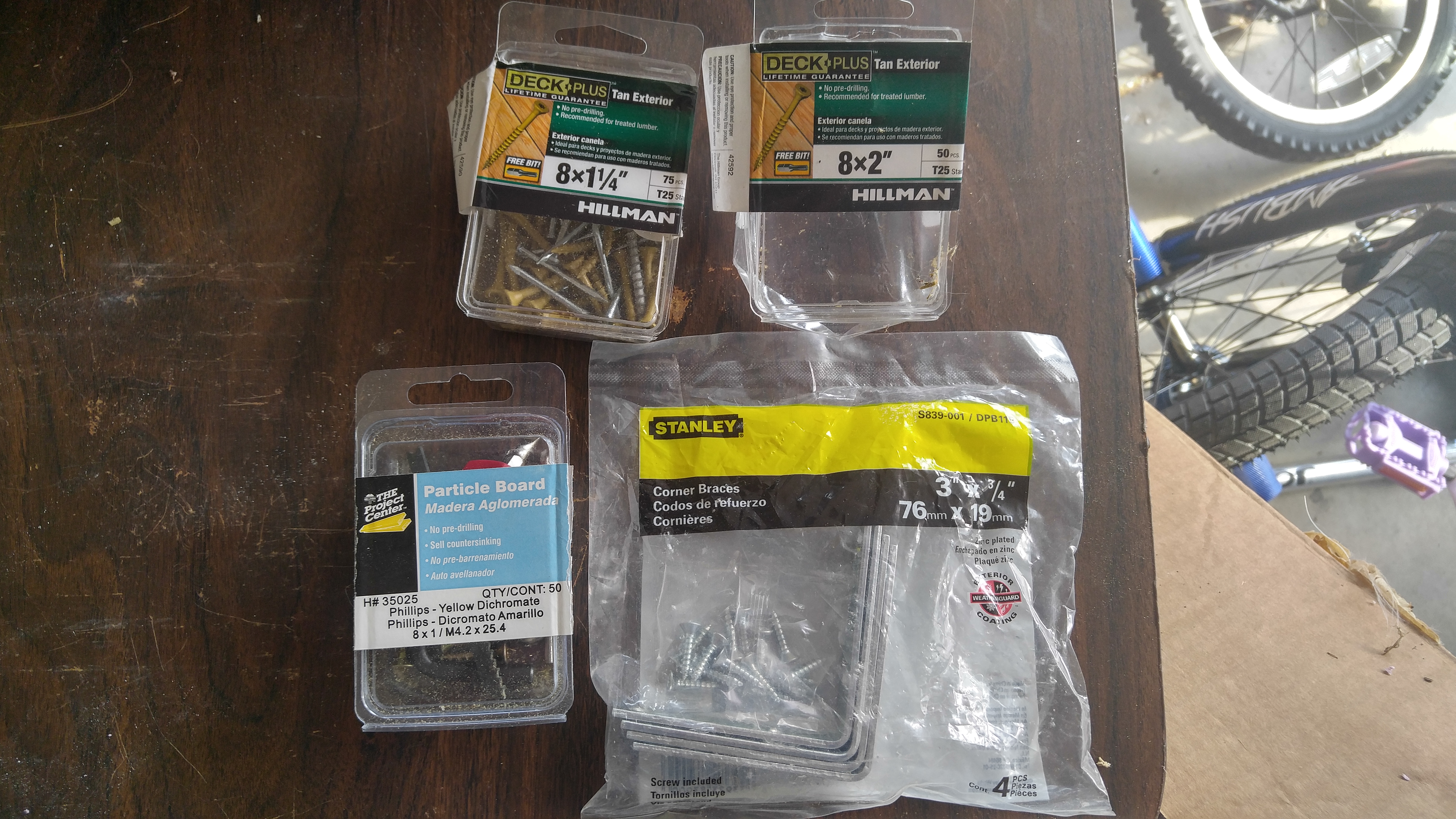
- (26) 3″ x 3⁄4” Metal Corner Brackets
- (2) 18″ x 24″ Thin Plexiglass Sheets
- (1) 2′ x 4′ Thick Plexiglass Sheet
- (5) Waterfall Pond Foam Cans
- (1) 2′ x 8′ Mylar Sheet
- (3) 2′ x 4′ White Plastic Egg Crate Panel (Lowes or Home Depot – $2 cheaper at Home Depot)
- (1) Box of DeckPlus 8 x 2″ Treated Lumber Screws
- (1) Box of DeckPlus 8 x 13⁄4” Treated Lumber Screws
- (1) Box of 8 x 1″ Particle Board Screws
- Circular Saw
- Jigsaw (Wood & Metal Blades)
- Needle Nose Shears
- Electric Screwdriver & Drill
- Manual Screwdriver w/Bits
- Razor Blade
- Scissors
- Heavy Duty Duct Tape
» Highland Chamber Construction
Step #1 – Cutting Wood to Size
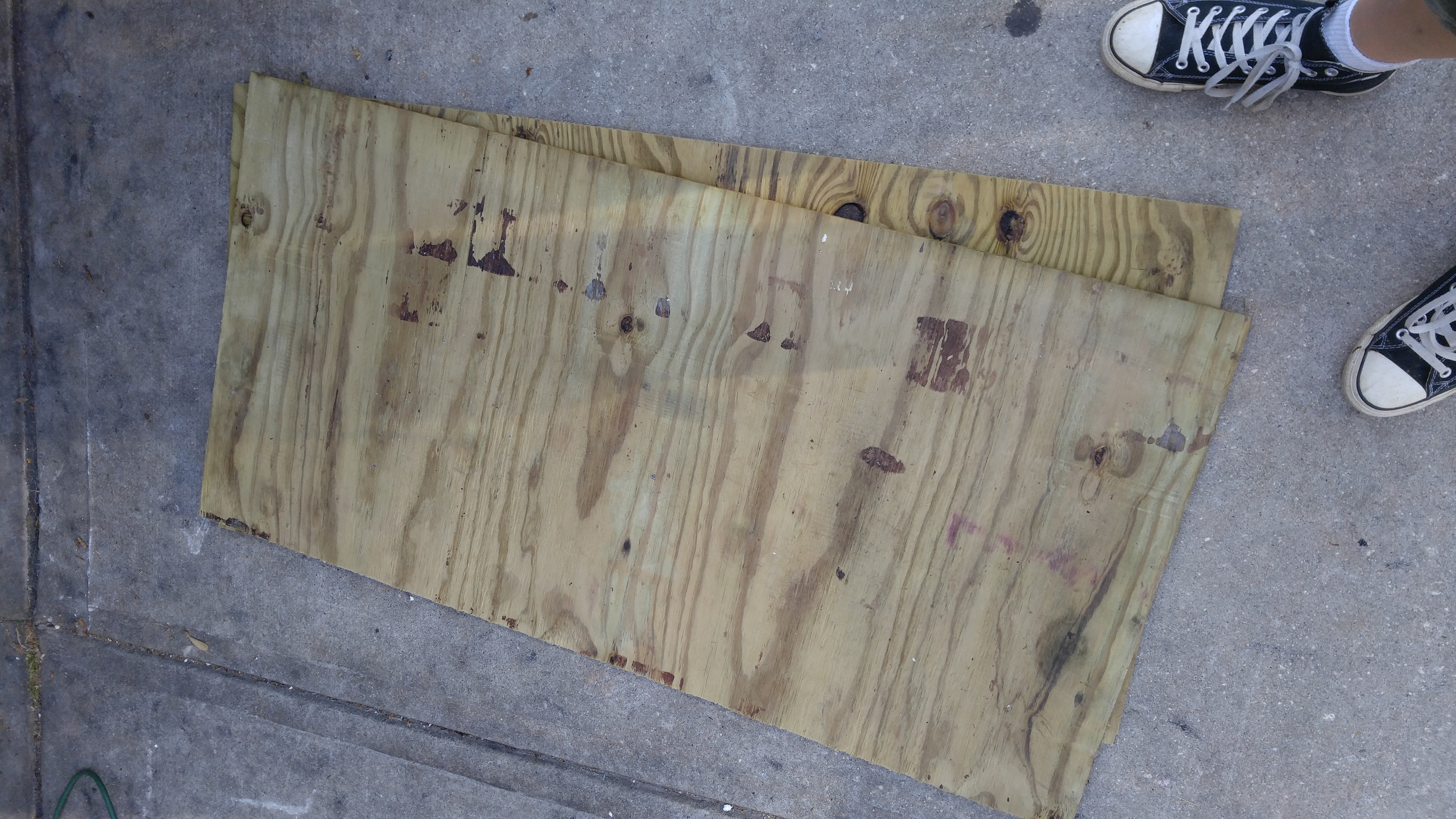
Special Notes: I used the plywood to construct the doors. In hindsight, this may not have been the best choice because it seems to warp easily. The plywood is still good to use for the base of it, but you may want to consider some kind of cabinet quality wood for the doors to get something that will make a snug seal.
Step Materials
- (1) 4′ x 8′ Sheet 1⁄2” Weather Treated Plywood
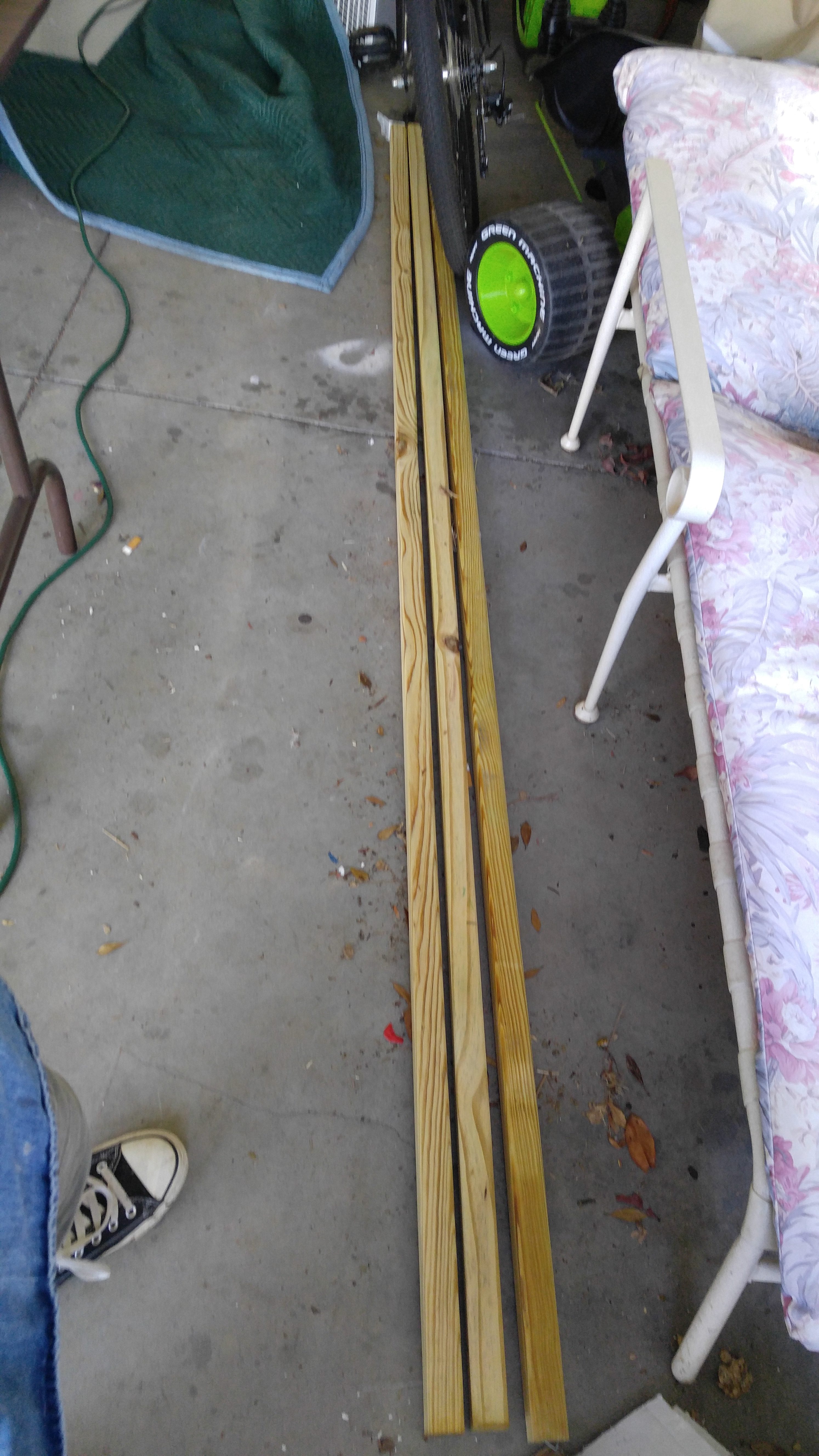
- (8) 2″ x 2″ x 8′ Weather Treated Boards
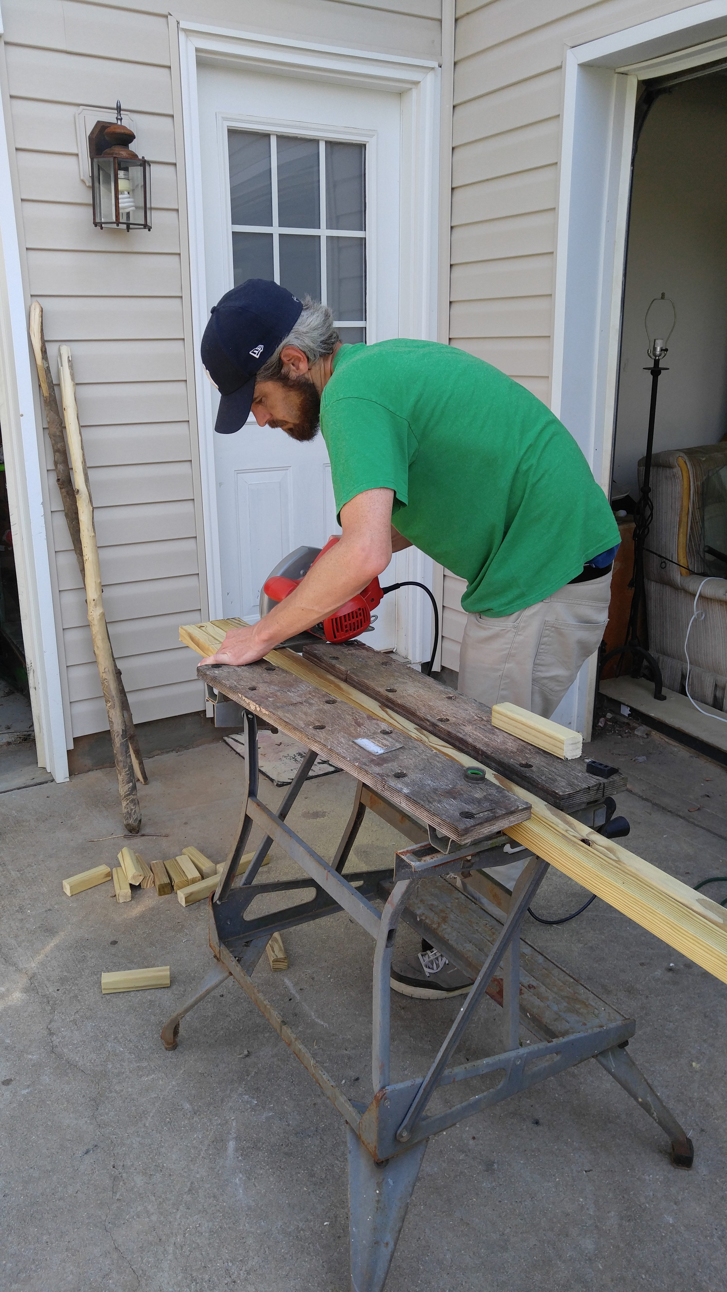
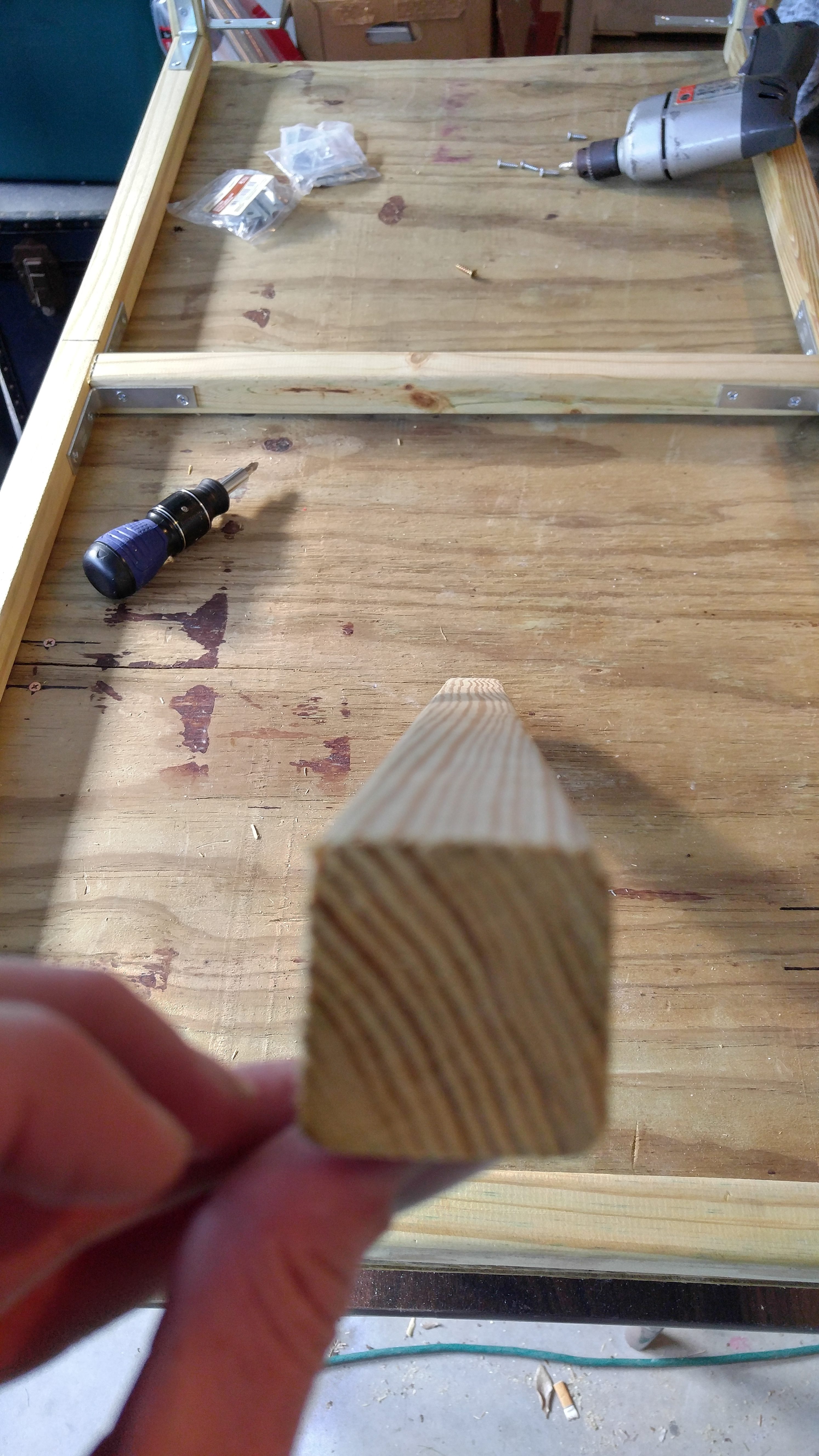
The 2″ x 2″ boards will be used to build a frame, support beams and legs for the box. I highly recommend that you start with your large cuts first and work your way down. Plan the cuts ahead of time to make sure you’ll be able to do all of them with the three boards.
You’re going to need four boards to make the corners of your box. These need to be exactly 2.5 feet tall (30″).
Next you’ll need 14 support beams of two different sizes. Six of these will be 45 1⁄4” long and eight will be 21 1⁄4” long. However, be sure to read the note below about the sizes of these support beams.
PLEASE NOTE: DO NOT trust the advertised size of your lumber! My 2″ x 2″ boards are actually 1 5⁄16” x 1 5⁄16“. You’ll have these boards going from the base to the top in each corner of the box. You’ll then connect boards the inside of these corner boards. To get the measurements of these additional boards (the 14 support beams), you’ll need to subtract the width of two boards from 48″ and then from 24”. For my long boards, this gives me 48″ – 1 5⁄16” – 1 5⁄16” = 45 1⁄4” (45 4⁄16“). For my shorter boards, this gives me 24” – 1 5⁄16” – 1 5⁄16” = 21 1⁄4“. Before you make these cuts, please check the width of your boards – if they are not exactly 1 5⁄16” wide then you will need to calculate new dimensions for your cuts.
I created feet for my grow box so it could sit on top of a chest freezer, which was my initial cooling method for this chamber. The freezer would have 4″ ducts coming out of the top, so I needed 5″ of clearance between the freezer and the bottom of the box. For stability, I made legs out of four pieces of these 2″ x 2″ boards, but two of these four boards were 1″ shorter than the other two. This allowed two of the four leg pegs to sit on top of the freezer while the other two braced against the outside of the freezer – this simply prevented my chamber from being able to slide around on top of the freezer.
With that said, if you are going to use my water cooling method, you do NOT have to create legs for your box unless you want to do so. If you were not going to fit these legs on top of a freezer, you would want to make 16 leg pegs that are all the same length (instead of half of them being 1″ shorter).
Lumber Cut List
- (1) 4′ x 2′ Plywood
- (2) 2′ x 22.5″ Plywood
- (2) 2′ x 7.5″ Plywood
- (2) 4′ x 7.5″ Plywood
- (4) 2.5′ x 2″ x 2″ Boards
- (6) 45 1⁄4” x 2″ x 2″ Boards (See Note Above)
- (8) 21 1⁄4” x 2″ x 2″ Boards (See Note Above)
- (10) 6″ x 2″ x 2″ Boards
- (8) 5″ x 2″ x 2″ Boards
Step #2 – Leg Assembly & Placement
Step Materials
- (8) 6″ x 2″ x 2″ Boards
- (8) 5″ x 2″ x 2″ Boards
- (1) 4′ x 2′ Plywood
- Heavy Duty Duct Tape
- 8 x 1″ Particle Board Screws
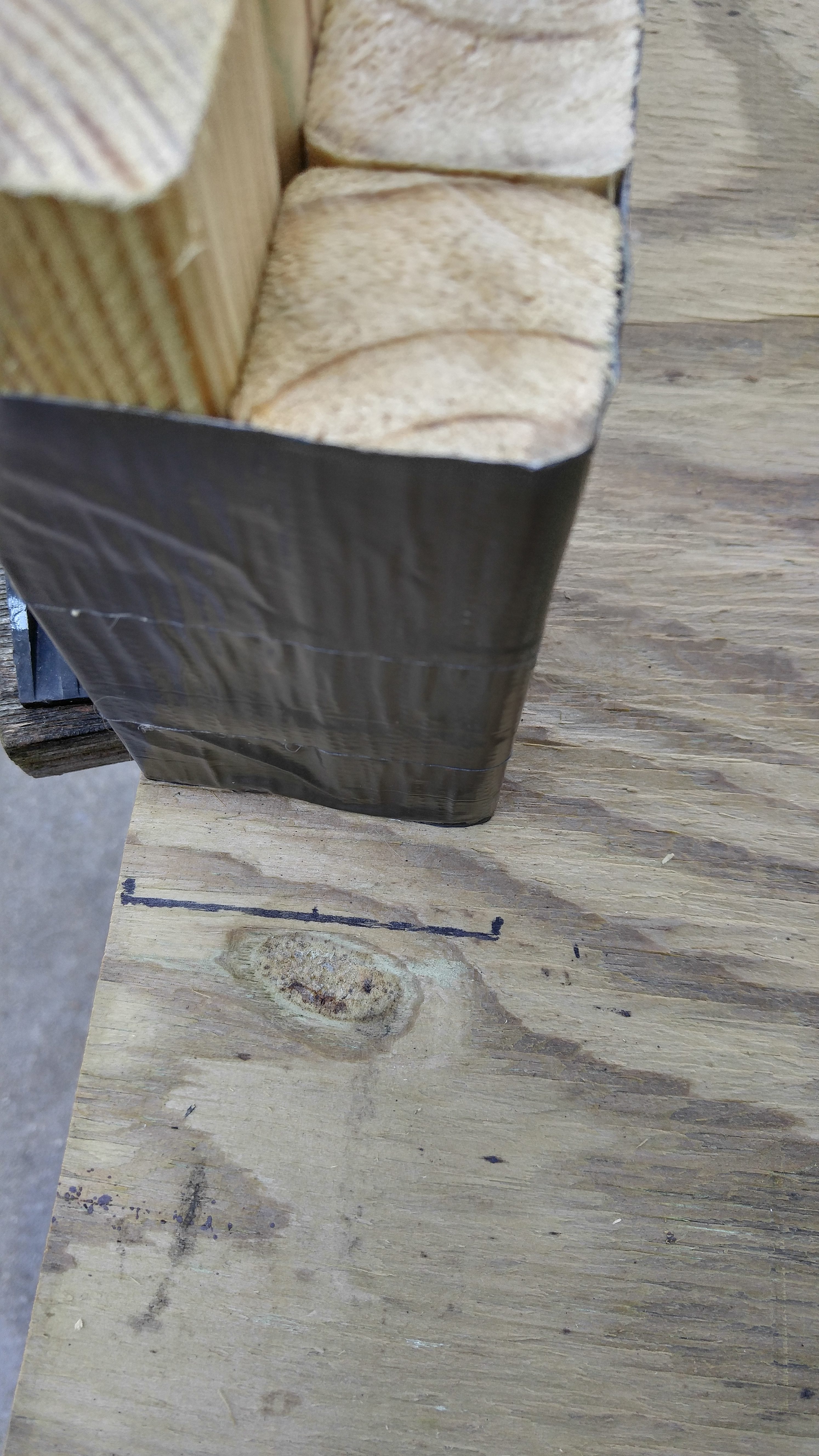
First construct the legs. Take two of each leg peg size (6″ and 5″) and arrange them in a square – the short pegs should be on one side of this square and the long pegs on the other side. Stand these four pegs up on a flat surface so that the bottom of the pegs are even, and then generously wrap duct tape around them to hold them together.
You’ll need to repeat this process four times to create the four legs.
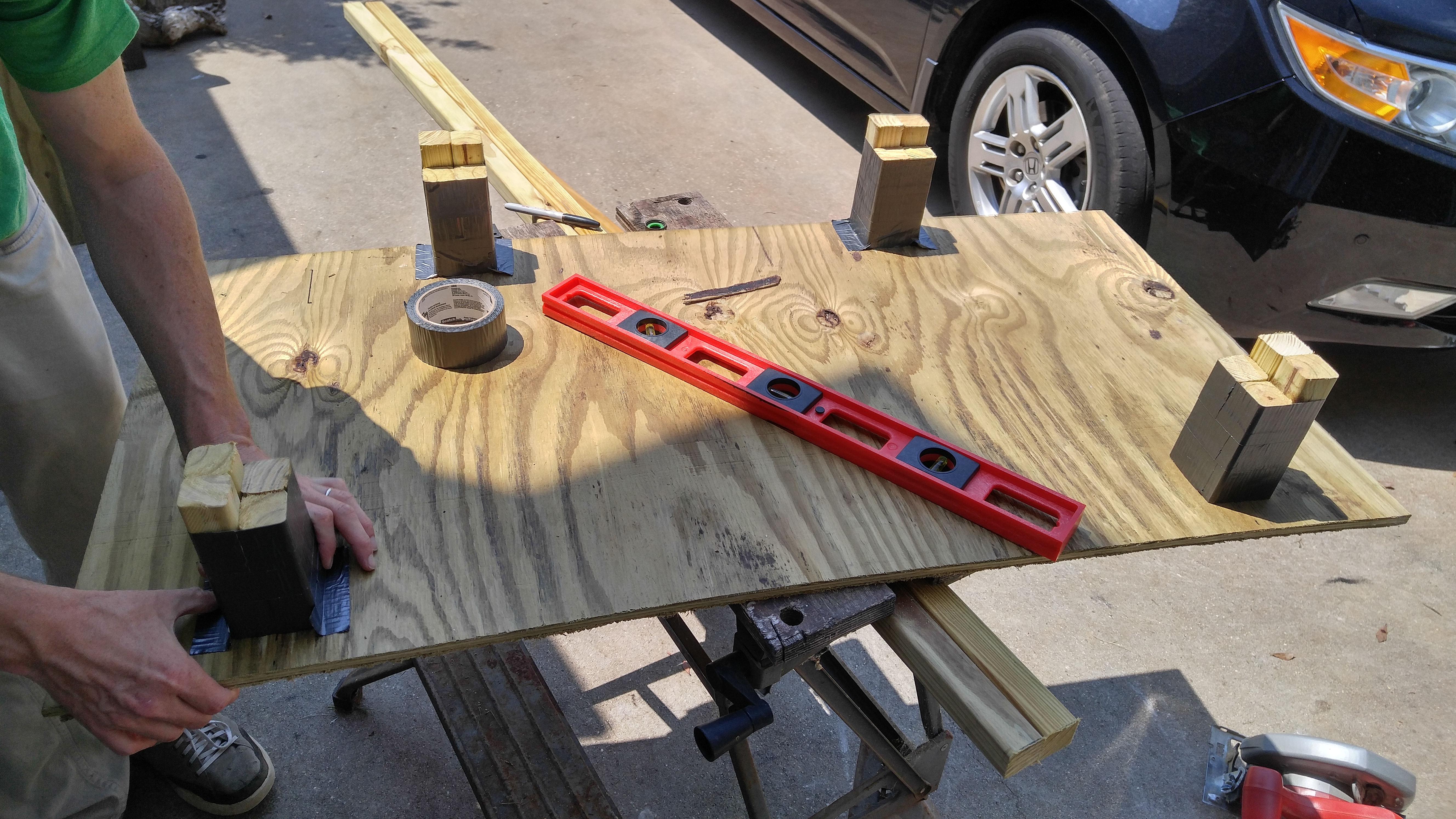
With all four legs are duct taped in place, flip the whole thing over so the board is sitting on the legs. You can also take this opportunity to make sure your leg placement is correct before you permanently attach them. If your placement looks good, try to make some measurements to determine the middle of each leg peg.
For example, if your leg block begins an inch from the edge of the plywood and your leg pegs are 1 5⁄16” wide, then your first peg center point would be around 1 21⁄32” from the edge of the plywood. The next would be 1 5⁄16” past that. These center measurements don’t have to be exact, but you’ll avoid splitting leg pegs if you get it pretty close.
Finally, once you have your leg peg centers marked, just put a plywood screw into each mark. Be careful when using electric screwdrivers here because they can easily drive a screw halfway into this plywood if you do it at full power.
Step #3 – Frame Assembly
Now it is time to build a wooden frame. It will sit on top of the plywood base that you just attached the legs to, but you do NOT want to actually attach the frame to the base until you finish building it (at the end of this step). I highly recommend you get a second person to help you with this step to ensure you build your frame straight and to simply make it easier on yourself during assembly.
Step Materials
- (4) 2.5′ x 2″ x 2″ Boards
- (6) 45 1⁄4” x 2″ x 2″ Boards (See Note in Step #1)
- (8) 21 1⁄4” x 2″ x 2″ Boards (See Note in Step #1)
- Metal Corner Brackets
- DeckPlus 8 x 2″ Treated Lumber Screws

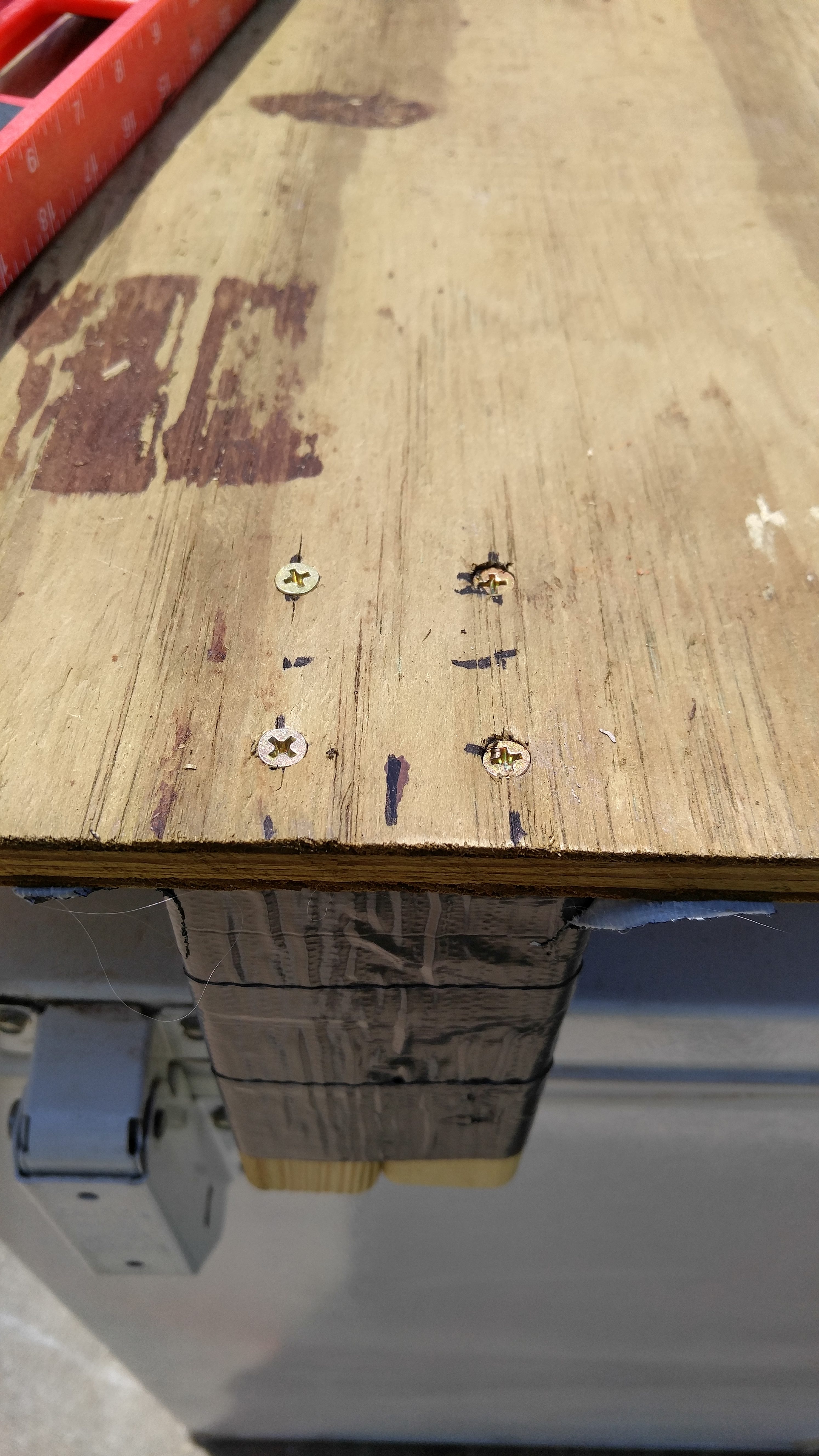
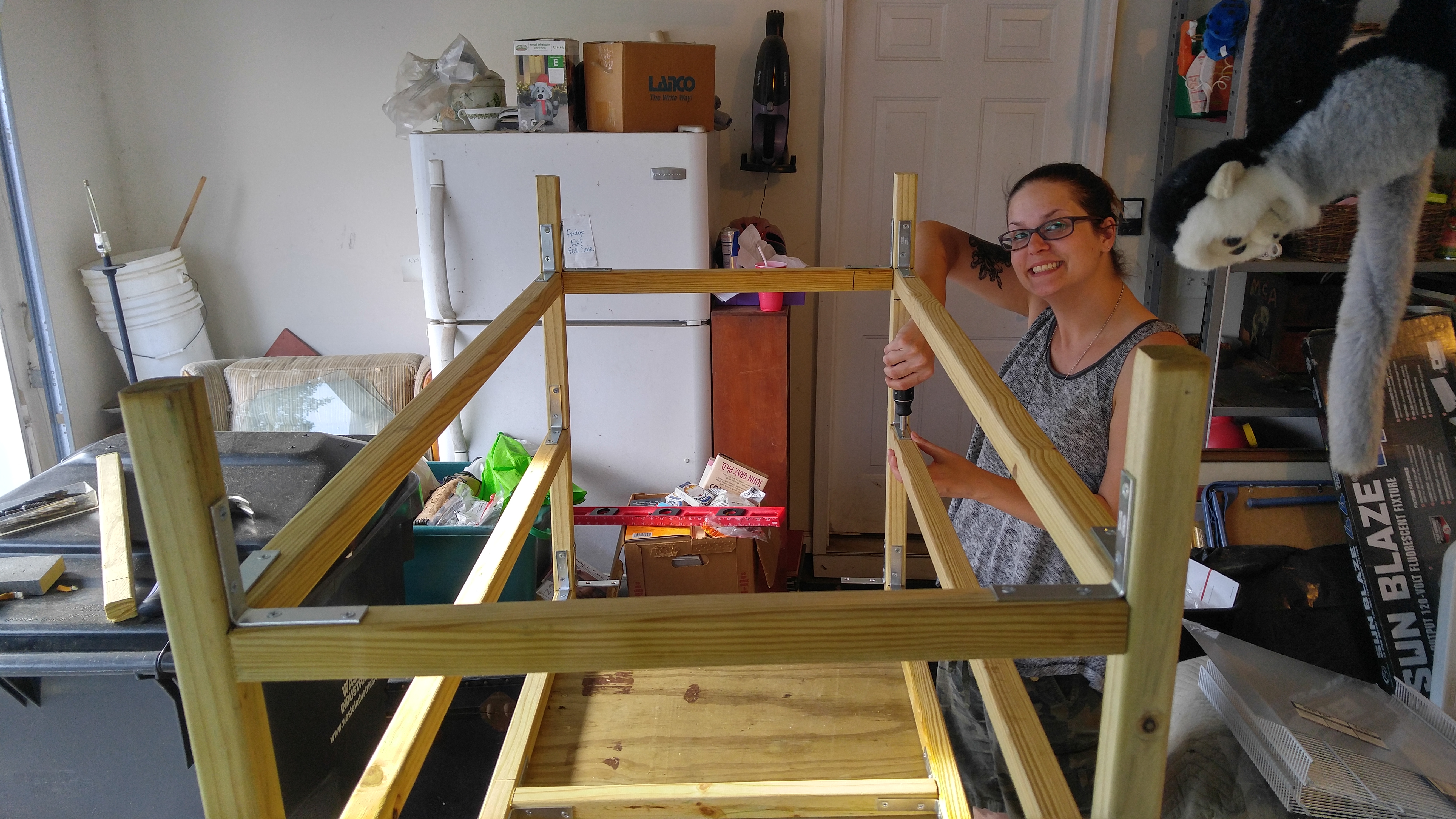
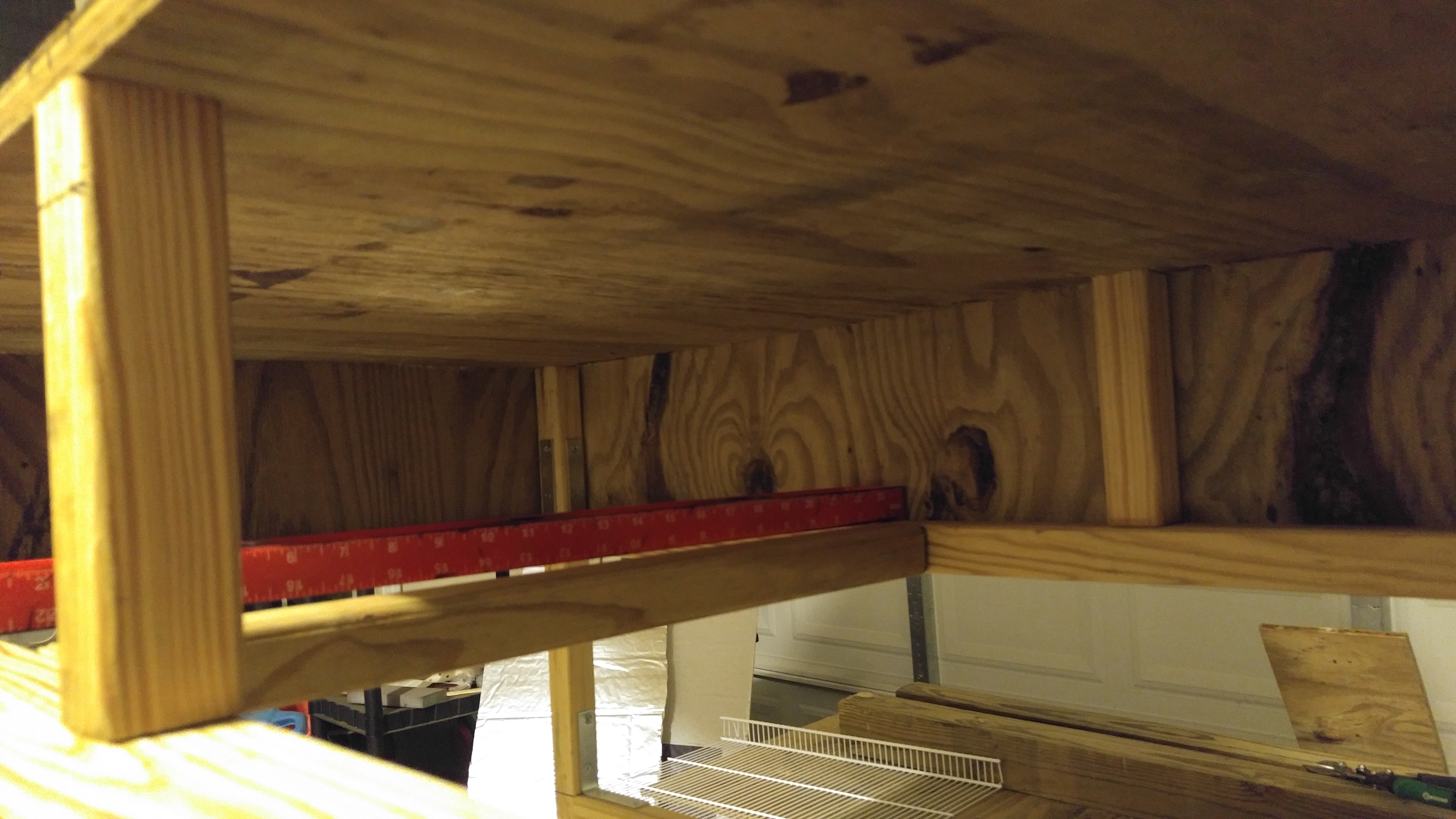
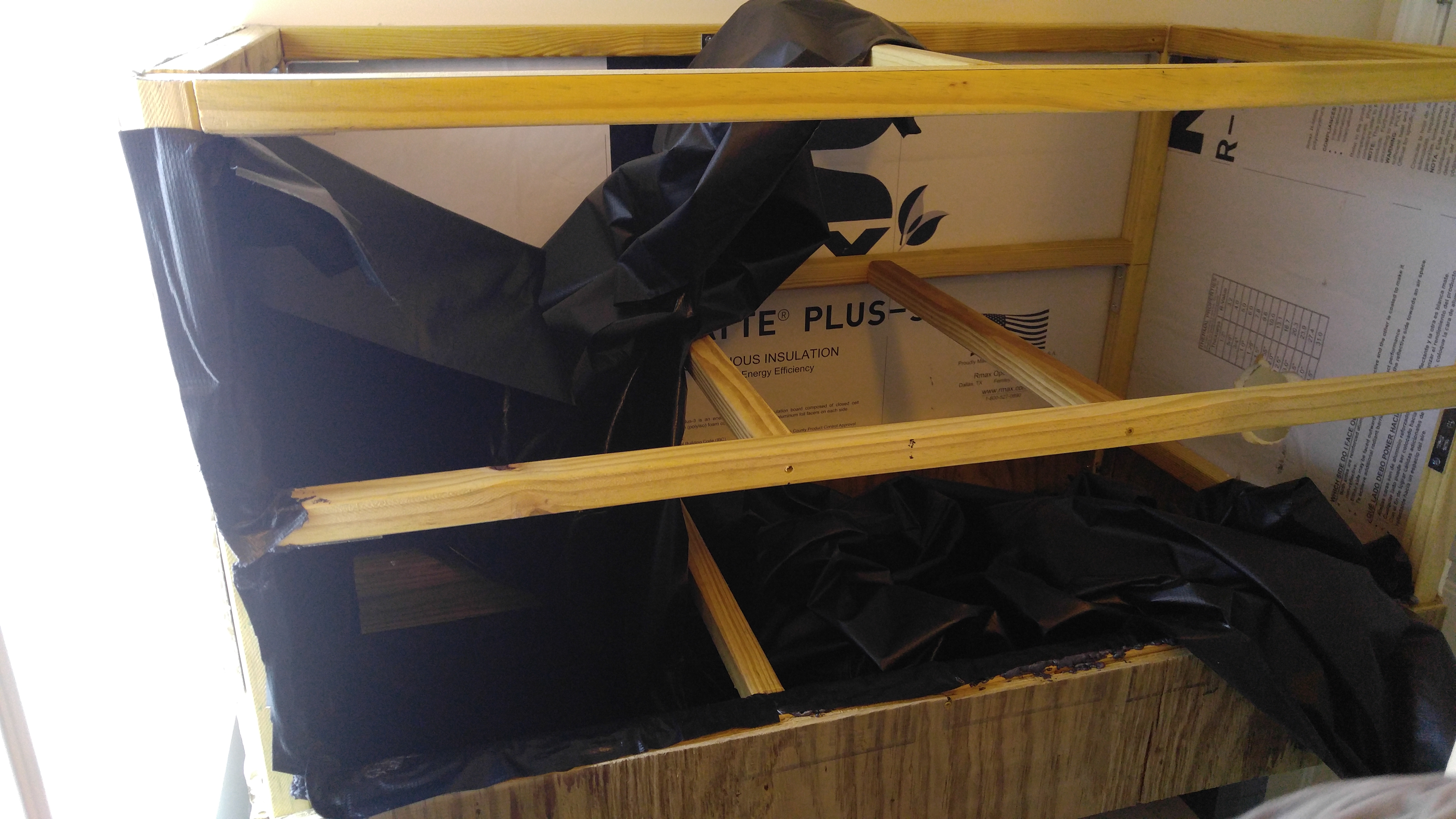
You’ll put three brackets going up one side of each board and then two more brackets going up another side of the same board (ie, if you lay the board down flat, put 2 brackets on the side facing up towards you and then 3 more brackets on one of the remaining sides but not the opposite side that is facing down). You can see this done in the first picture here on the right.
A 2×2 board will end up sitting on top of each of these brackets and will help support part of the chamber. The bottom bracket will support a board that marks the top of the reservoir and the bottom shelf. The second bracket will support a board that will hold the middle shelf. The top bracket will support a board that will hold the large sheet of plexiglass, which will be the top of the chamber.
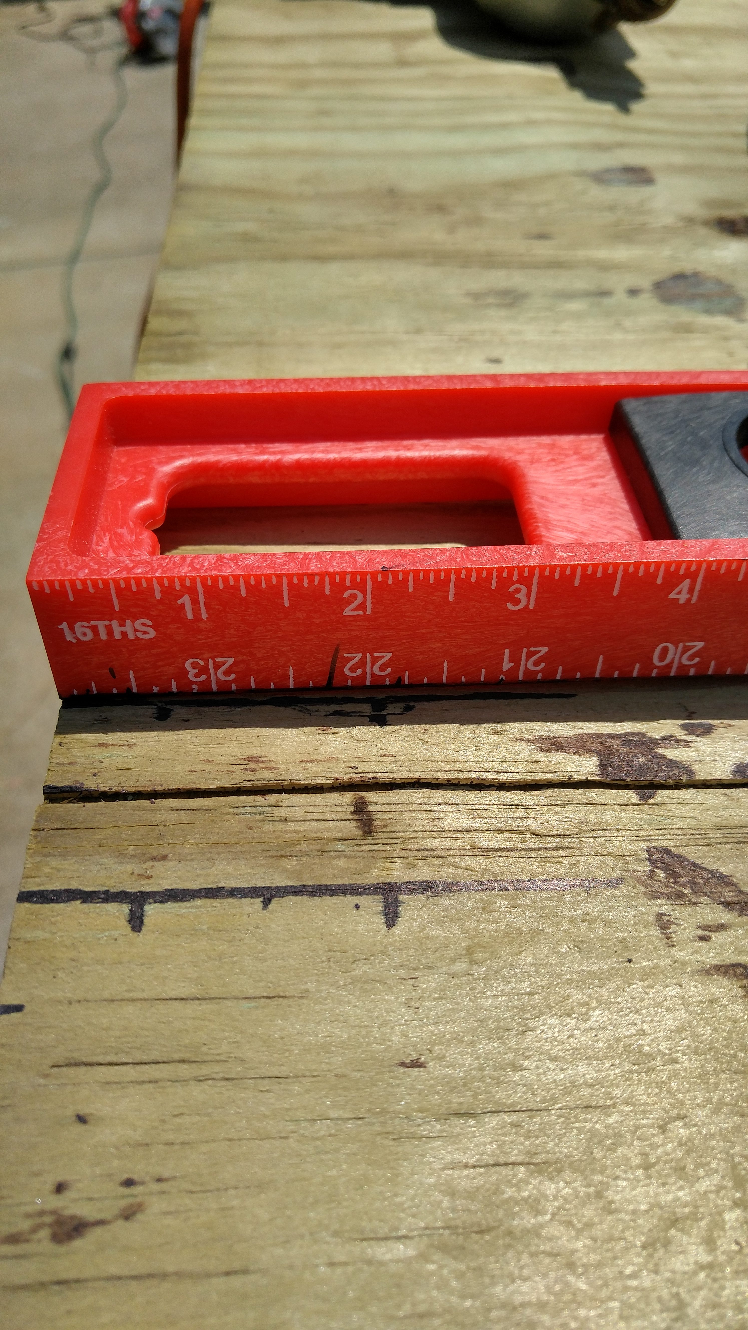
Lay out the four 2.5′ tall boards all facing the same direction to ensure you get the brackets right. Make measurements on these boards going from the bottom up – you’ll want to mark 6″, 17″ and 28 11⁄16” with a horizontal line. Remember that you’ll be making these marks on two connecting sides of each of those four boards, but the middle mark (17″) will only go on one side. That last measurement is the most important and is based on the exact width of the 2×2 (mine is 1 5⁄16“) – when you put a board on top of the bracket, it should be flush with the top of the corner board.
Each of those marks is where you’ll put a bracket. The corner of the bracket will touch that mark – just try to center the bracket on the face of the board. Each corner board will get 5 brackets for a total of 20 brackets to use at this point.
In the first picture directly above on the right, note how the two boards with brackets have the three bracket sides facing each other and the two brackets on the connecting side are sticking straight up. Arrange two boards like this, and then proceed to attach three of the 45 1⁄4” x 2″ x 2″ boards between them. Each board sits on top of a set of brackets, and then you simply put two screws into each bracket to attach it. Repeat this same process with the other set of boards with brackets. When you’re done with this step, you should have two walls of your frame built.
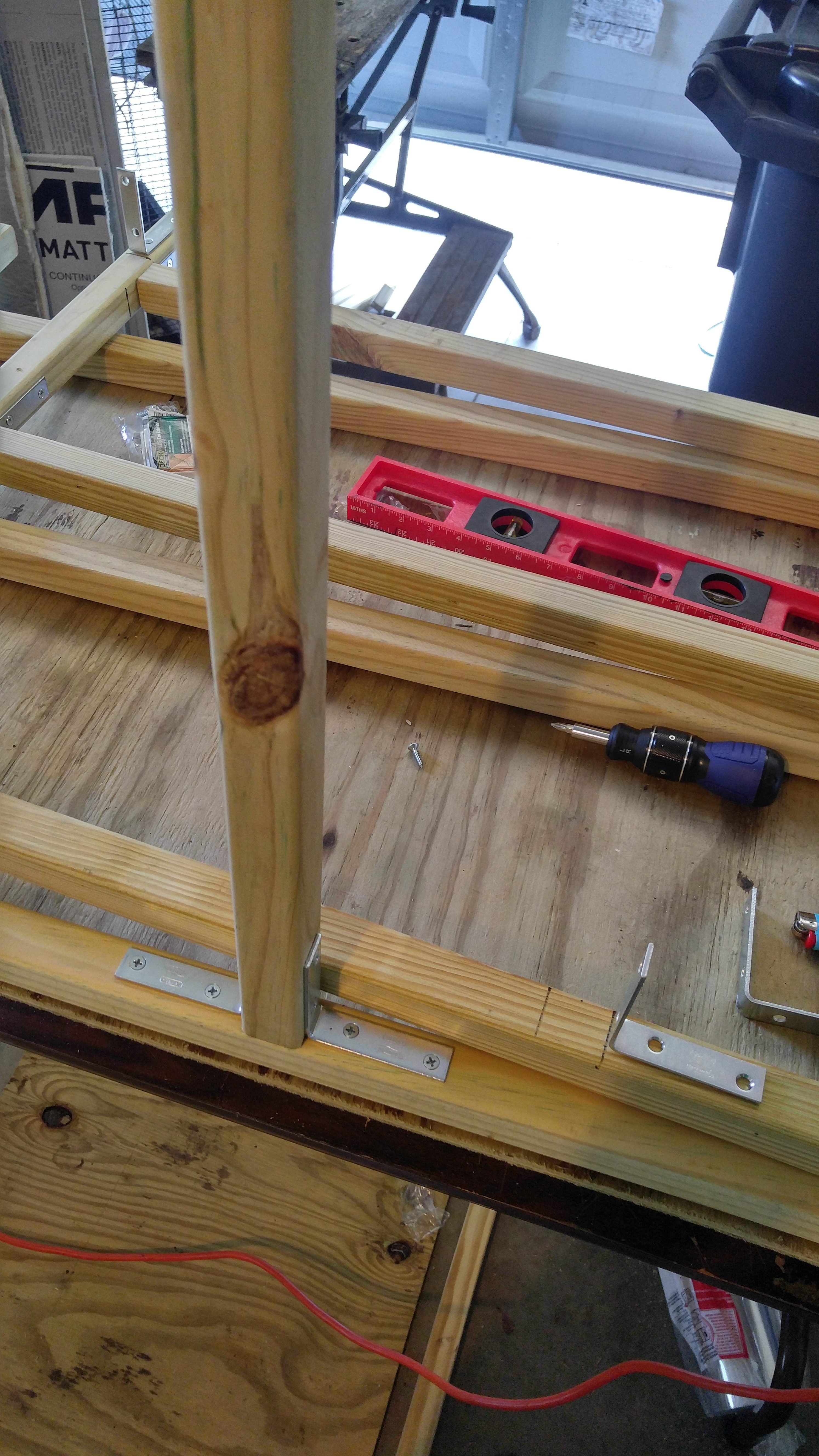
To install the brackets, first mark a halfway point on the 45″ 1⁄4” top board – 24″ if you measure from the side of the outside of the frame. Then mark two lines on this board near that halfway point – these two lines should be half of the width of your board away from the mid point (21⁄32” from middle).
Put the corners of brackets up against those lines and attach. Hold a 21 1⁄4” x 2″ x 2″ board in place before attaching the second bracket to ensure you have the right space between the two brackets for the board to fit snugly between. With the brackets in place, go ahead and screw them into the 21″ board to connect it.
Repeat the same process on the other wall except only attach one bracket and no board (but make lines for both brackets). You’ll eventually attach this to the other end of the board you just connected on the other wall. For this, put this wall aside and go back to the wall with the 21″ board already attached.
Now take four more 21 1⁄4” x 2″ x 2″ boards, stand them straight up and attach them to the four remaining brackets on the corner boards for this wall. With this done, you should now have five of these 21″ boards sticking up from the one wall.
Stand the wall up but upside down (a 45″ and three 21″ boards should be flat on the table). Then stand up the second wall with the open brackets facing the first wall. Push these walls together and connect all of the remaining brackets. Also be sure to add the second bracket to the top board of the second wall (this board is flat on the table now) – you should already have a mark made for this bracket.
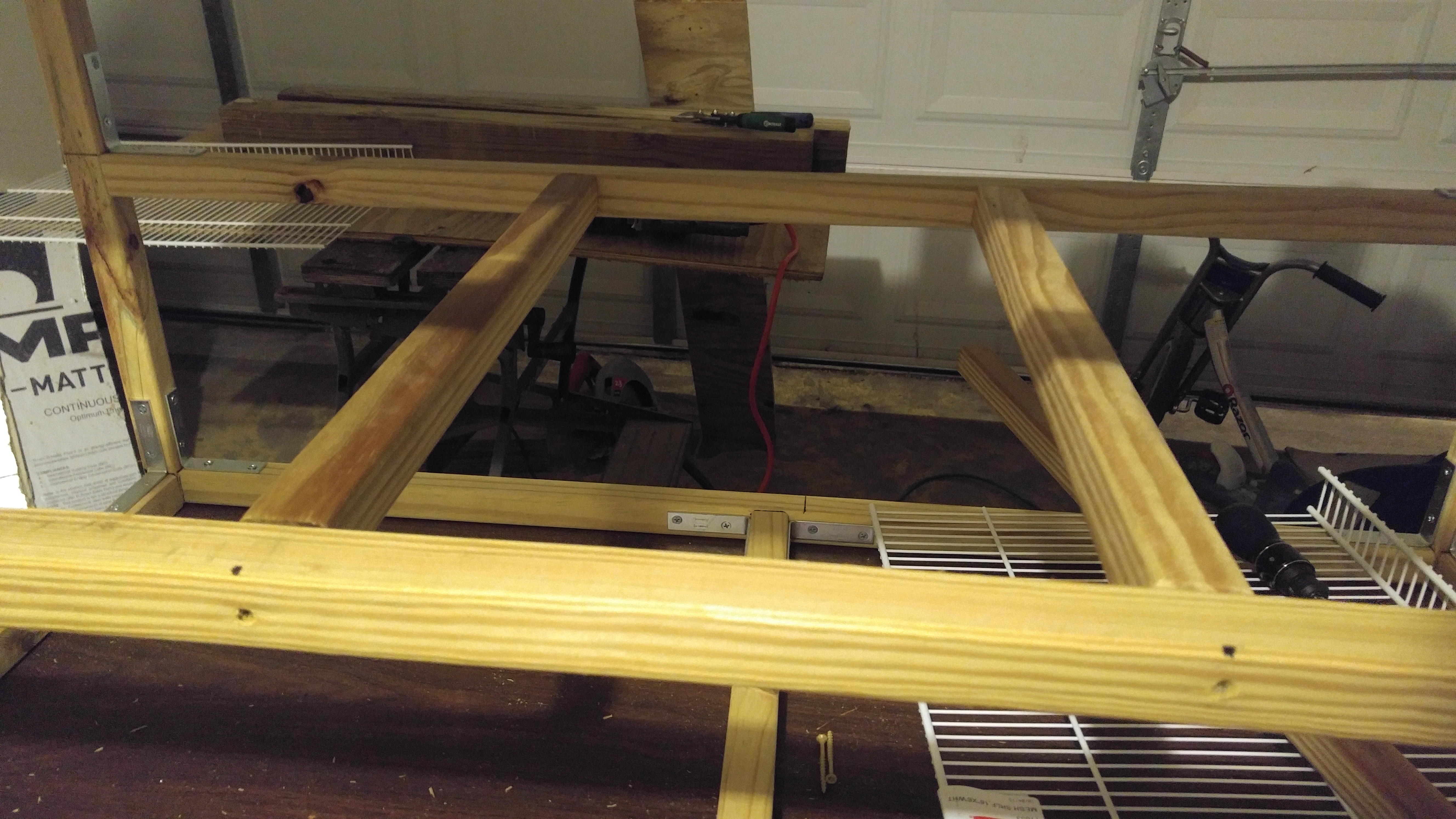
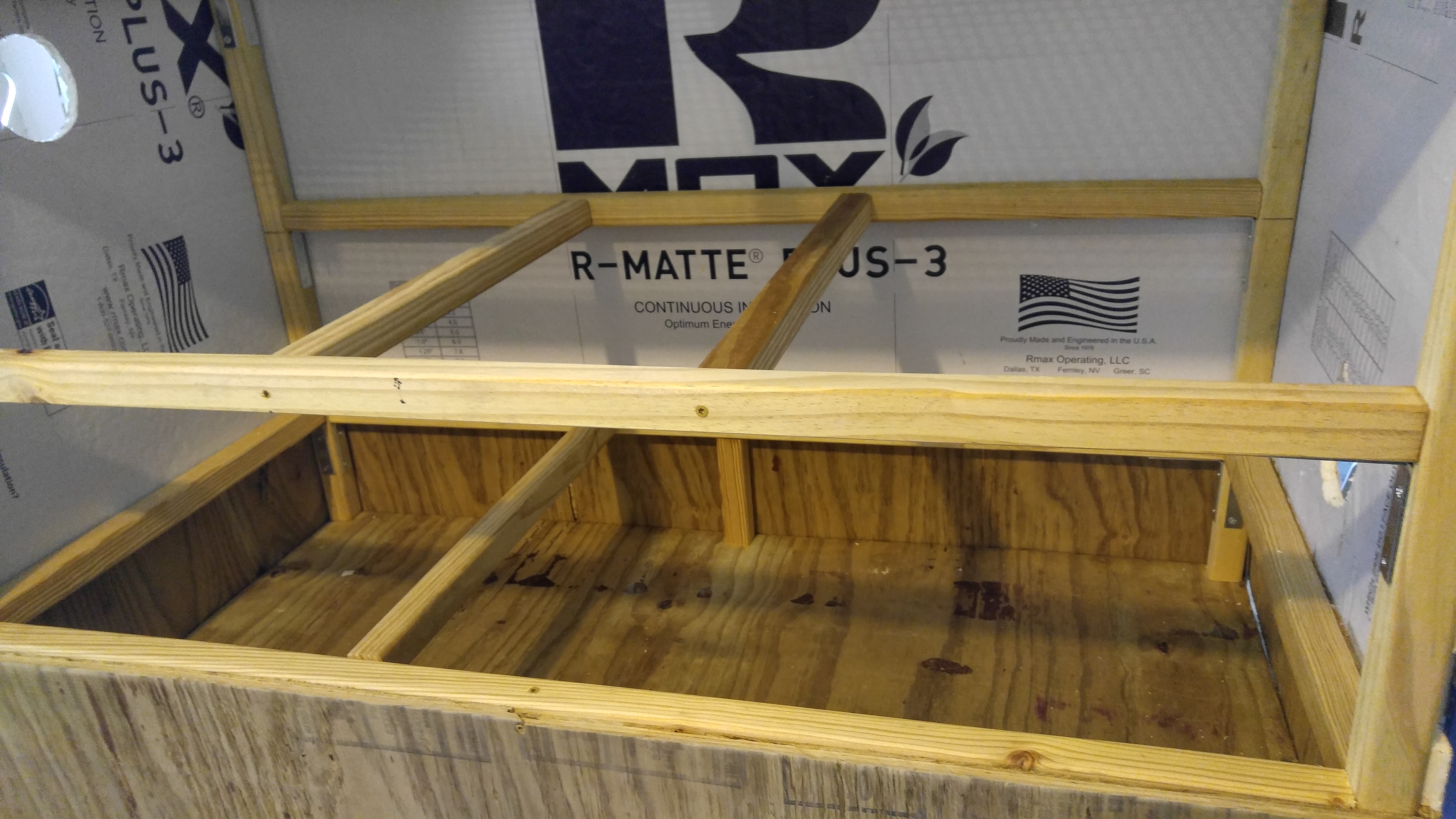
Once you connect all of these brackets, the outside of your frame is finished! You should basically have what you see in the picture below.
You should now be left with three 21 1⁄4” x 2″ x 2″ boards – these will be support beams that go inside of the box. These beams will end up providing additional support for the shelves that the plants will sit on.
Your frame should still be upside down at this point, as seen in the picture above. One of these support beams will go between the 45″ boards that are currently at the top of the frame. The other two will go between the middle 45″ boards.
Start with the middle board. It will get two support beams to split this area into thirds. Measure the middle 45″ 1⁄4” board and make two marks that will cut it into thirds (marks 16″ 11⁄12” apart). Do the same on the opposite middle 45″ board.
The third 21″ support beam will go between the top 45″ boards (the only two 45″ boards that do not already have a 21″ board attached to it). You could technically do two support beams here just like you did above, but I opted for one to make the construction easier and also to allow more room to get into that bottom section of the chamber (which will be a water reservoir).
Even with one support beam, I still recommend using the same measurements as you used with the previous beams – putting the support beam a third of the way through the 45″ board. Do the same as you did with the other two support beams – measure, mark, put the beam in place and then screw both ends to attach.
At this point, your frame is fully assembled. It should be very study and stable – if not, check your brackets to make sure they’re all tight.
WARNING: Once you proceed beyond this step, many parts of this frame will quickly become inaccessible. For this reason, be 100% sure that it’s complete and you’re satisfied before you continue.
Step #4 – Reservoir Assembly
With the frame completely done, we’re going to attach it to the chamber base and also assemble the other sides of the bottom of the chamber, which will be a water reservoir.
Step Materials
- (2) 2′ x 7.5″ Plywood
- (2) 4′ x 7.5″ Plywood
- (2) 6″ x 2″ x 2″ Boards
- 4 Metal Corner Brackets
- DeckPlus 8 x 2″ Treated Lumber Screws
- 8 x 1″ Particle Board Screws
Your frame should still be sitting upside down with the four corner pegs sticking up in the air. Grab the base you constructed earlier, turn it upside down and place it on top of the four corner pegs. You want those pegs to line up with the corners of the base. Once you have the base in place, put a long screw down through the plywood base and into each of the corner pegs – aim for the center of the peg.
Now take the two 6″ x 2″ x 2″ boards. They go between the base plywood board and the long 45″ bottom board that will be at the top of the water reservoir. These two 6″ boards should be positioned in the center of those 45″ boards to act as support beams. Simply screw these in place on both ends.
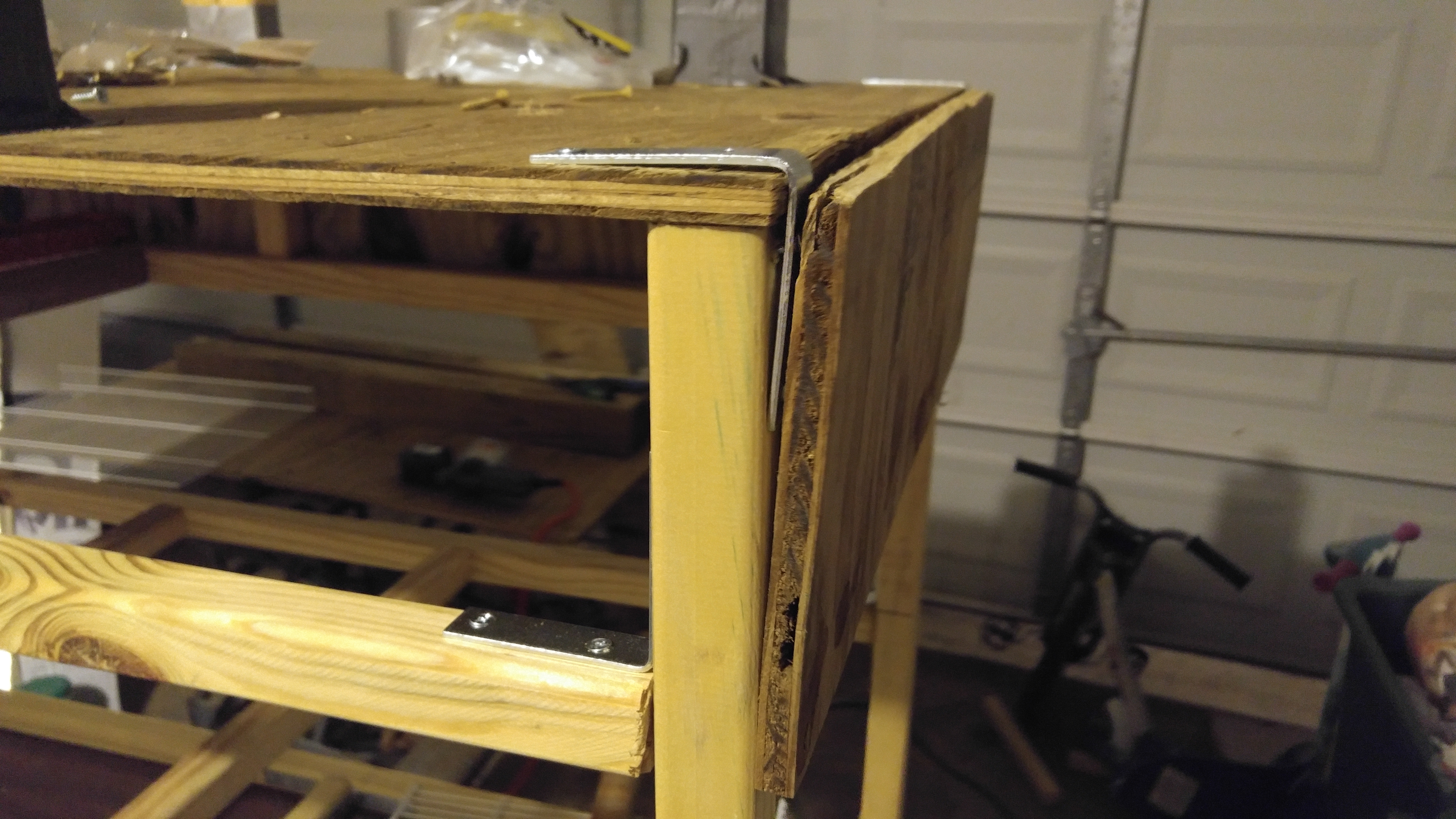
At each corner of the grow chamber, you’ll want to add a bracket and connect that bracket to the corner leg. Make these brackets face the left / right sides of the chamber and not the front / back. This way you only have to worry about the plywood gap on two panels.
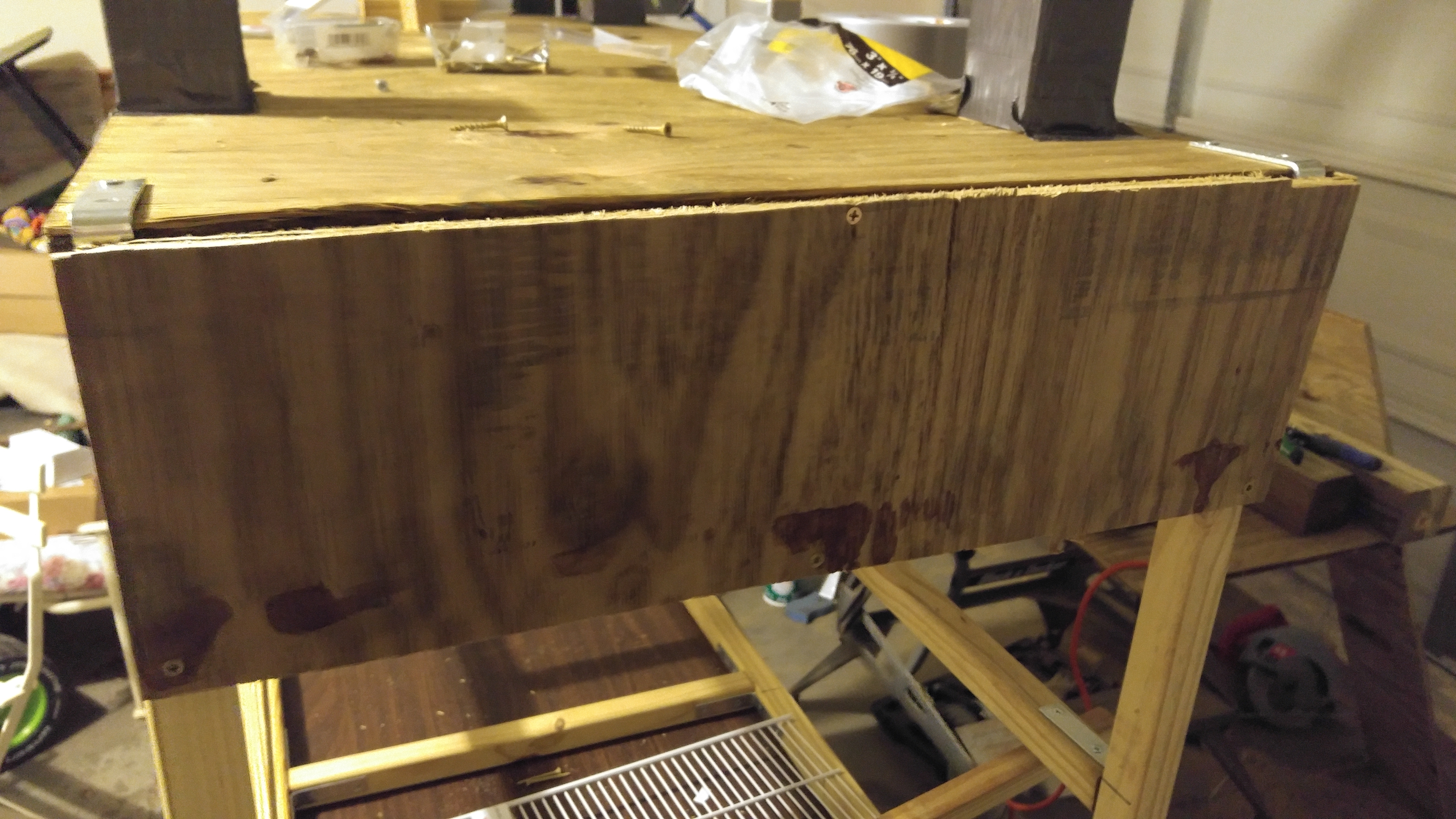
The four remaining plywood pieces are going to be used for the reservoir panels. The 4′ boards go on the front and back, and the 2′ boards go on the left and right sides.
When you’re attaching these boards, line them up on the top with the plywood base before screwing in place. This means that the plywood will completely cover the side of the plywood base. However, it won’t actually cover the entire side of the top 2×2 board (it will cover about half to three quarters of it – the doors will end up covering the rest).
If you have brackets under the 2′ plywood panels, you won’t be able to put screws into those bottom corners. On these panels, try to get screws in fairly close to where the bracket will be under it but not close enough so that they make contact. I went a bit heavy with screws on these side panels to get them to sit flush against the chamber side as much as possible
Step #5 – Insulation Installation
For this step, you’re going to insulate your grow room. The place where I wanted to put my chamber is very limited in space, so I went fairly minimal with my insulation. However, with more room, I would likely do more. Keep in mind that how much insulation you put on this chamber and also whether you have gaps between the insulation can end up affecting your energy efficiency – with less insulation, you simply use more cooling power at night to reach lower temps and also to maintain them.
Step Materials
- (1) 4′ x 10′ Sheet 1⁄2” Foam Insulation Board
- 8 x 1″ Particle Board Screws
At this point, nothing really differentiates the various sides (ie, front / back, left, right). We’ll solve that now – first go ahead and flip your box right side up so it is standing on the legs. At the top of the water reservoir, you should have one support beam that goes across the inside of the chamber. That support beam is much more on one side of the box than the other – the side it is closest to will be the left side of the chamber. Position the chamber in front of you with that board on the left – this will also give you the front, back and right sides. The left / right sides are short (2′ long) and the front / back sides are long (4′ long).
Once you have the sides of the box worked out, you know what to insulation – the left, back, right and inside bottom.
Your insulation board is 4 feet wide, which is a good measurement to use for one side of these boards to make cuts easier. Going down the long side of the board, you’ll want to make three marks – at 2′, 4′ and 6′. Turn these marks into straight lines that go across the width of the board. Then cut these lines with an exacto knife / razor blade. This will give you three pieces that are 4′ x 2′ and a larger leftover piece (you won’t use this leftover piece unless you decide to insulate the door and/or the reservoir panels).
The first 4′ x 2′ piece should go on the back of the chamber. Put the reflective side out and screw it into place with plywood screws. Next, take another 4′ x 2′ piece and cut it in half to make two 2′ x 2′ squares. Attach these squares to the left and right sides in the same manner as the back piece.
You’ll want to put that full size board into the bottom of your grow chamber, but the support beam in it can make it difficult to fit it all at the same time so I cut it in half to fit it in. Once the corners are removed, you’ll want to cut this board in half just like you did the last one. Put one piece on the left side and the other piece on the right side. Push both down at the same time to get them to fit in place and stay (mine was a tight squeeze otherwise).
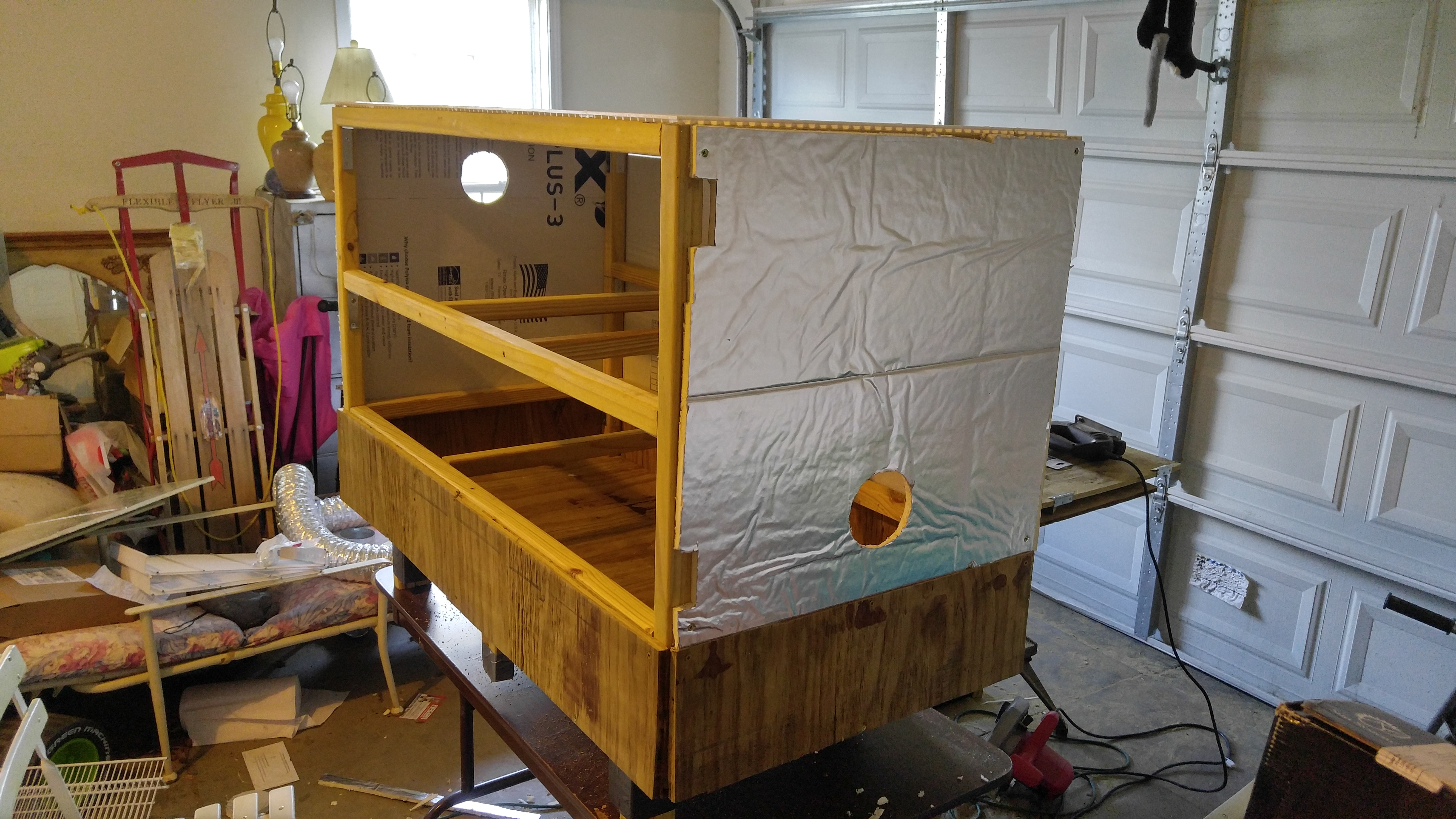
You won’t see it pictured here, but you may also need to cut out two more circular holes but 6″ this time. If you’re going to use my water cooling method, the intake and exhaust to recirculate growing air through the cooling system will use six inch ducting.
For me, I ended up putting both of these 6″ holes on the right side of my chamber. However, I did it this way because I had very limited area outside the box and couldn’t locate the ducts and cooling system anywhere else. If you will have roughly two feet behind your chamber then you may consider putting the 6″ ducts on the back or possibly one on the left and one on the right. No matter which side you put it on, make one hole on the top half and the other on the bottom half.
Additional Insulating
If you’re able to do so, I’d recommend getting the 2″ thick pink foam insulation board from Home Depot and using that in addition to the thinner board that I used. If you could enclose as much of the grow chamber as possible in a sealed box of that pink foam insulation, you would be able to retain cool temperatures much easier, so your cooling system would be much more efficient if your box was extremely well insulated. Think of this like putting your grow chamber inside of a cooler – it will simply be able to hold a cold temp longer. I wanted to do this but simply didn’t have enough room left around the box with it in place where I wanted it in my house.
To truly make the extra 2″ pink insulation layer effective, you’ll want to shoot to enclose all sides and the bottom without gaps in the insulation. At this point though, you won’t have doors on the chamber. The main issue with attempting this is that the door hinges prevent completely enclosing those corners (you’ll need to leave space for the doors to be able to swing open). However, if you can completely enclose the bottom, the left / back / right sides and the reservoir panel and possibly the doors on the front, that will certainly give you some good energy efficiency.
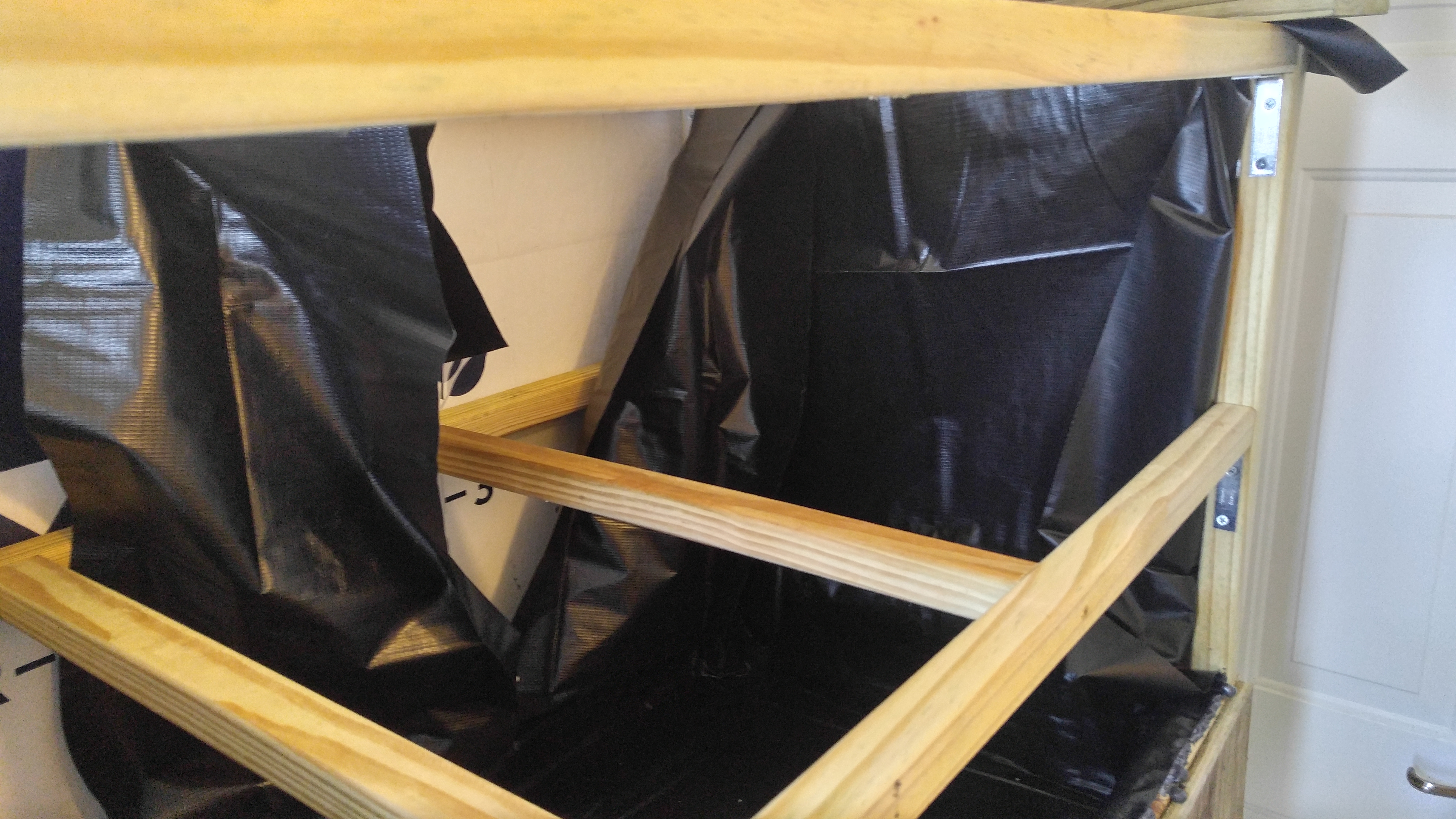
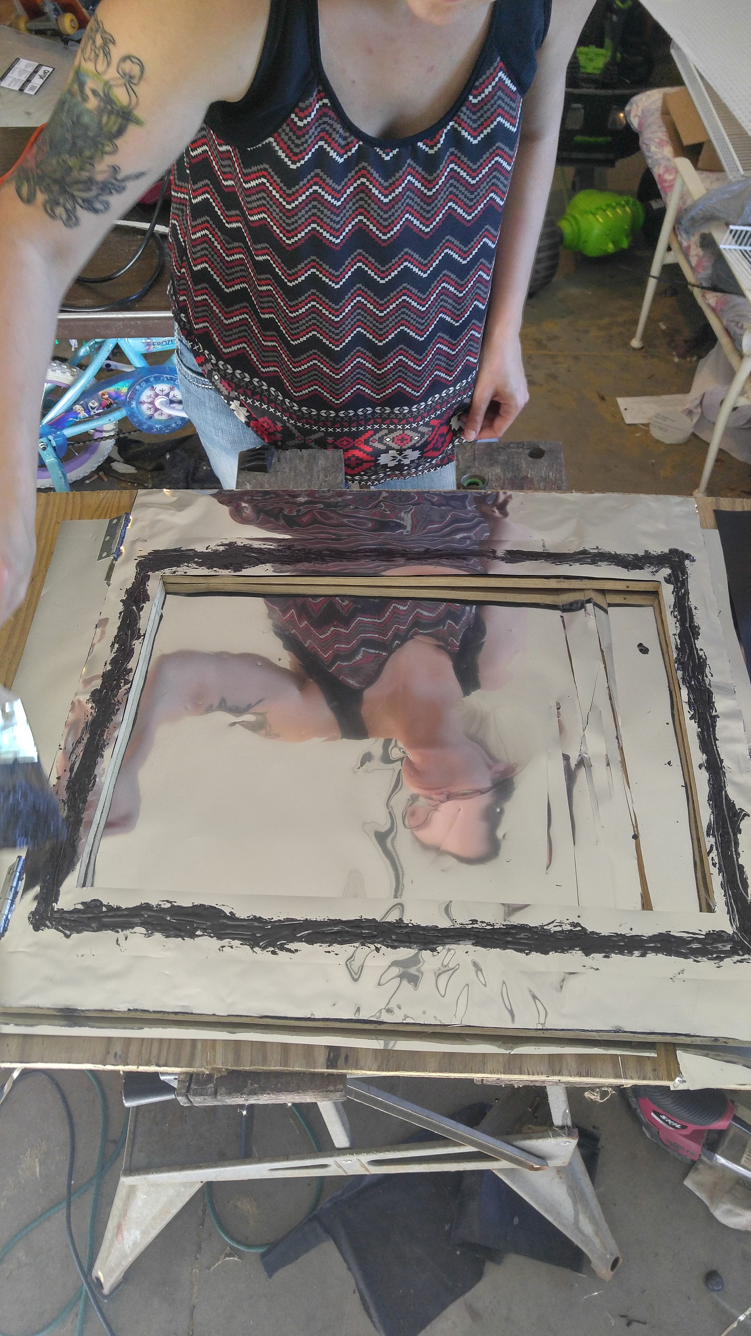
Step #6 – Waterproof Highland Chamber Interior
At this point in the project, I had spent most of the day out in the garage in the heat and was dying for some air conditioning. For this reason, I went ahead and moved the project inside and put it in place. In hindsight, it probably would’ve been a lot easier if I had left it in the garage until this part was finished because I had extremely limited room around the box so it made installing the pond liner difficult and time consuming.
Using a 7′ x 10′ pond liner, I was able to seal and waterproof the entire interior. I also later used excess pieces to line the inside of the doors to make the structure almost entirely waterproof, although water can leak around the bottom of the door unless you construct a lip there to force water on the front water reservoir edge to roll back into the reservoir.
Step Materials
- (1) Pond Liner Tarp
- (2) Waterfall Foam Cans
WARNING – USE DISPOSABLE GLOVES WITH WATERFALL FOAM – THIS FOAM WILL STAY ON YOUR HANDS FOR A WEEK OR MORE IF IT GETS ON YOU AND WILL PERMANENTLY STICK TO MOST OTHER SURFACES, ESPECIALLY CLOTHING. ALSO USE THE FOAM IN VERY LIMITED AMOUNTS. IT WILL EXPAND MULTIPLE TIMES IT’S ORIGINAL SIZE BY THE TIME IT DRIES. AFTER YOU SPRAY IT AND STICK THE TARP TO IT, GIVE IT A FEW MINUTES TO DRY THEN SMOOTH THE TARP OUT AGAIN – REPEAT THIS PROCESS A COUPLE OF TIMES UNTIL IT DRIES.
Another note about working with this waterfall foam. If it expands out too much, you can always wait for it to completely dry and then cut it away with a razor (just don’t cut your tarp).
You’ll want the edge of the tarp closest to you to line up with the front lip of box (where the bottom of the front opening for the doors begins). Try to get this roughly lined up when you’re spreading the tarp out in the box and work try to flatted the tarp out along the bottom of the box.
By doing this all the way up to the front lip of the reservoir and keeping the liner tight, you’ll be able to see if you have it lined up correctly. If needed, make some adjustments to the placement of the tarp so that it lines up with this lip as close as you can (a bit of overlap is okay but make sure it won’t fall short of covering the entire flat side of the lip.
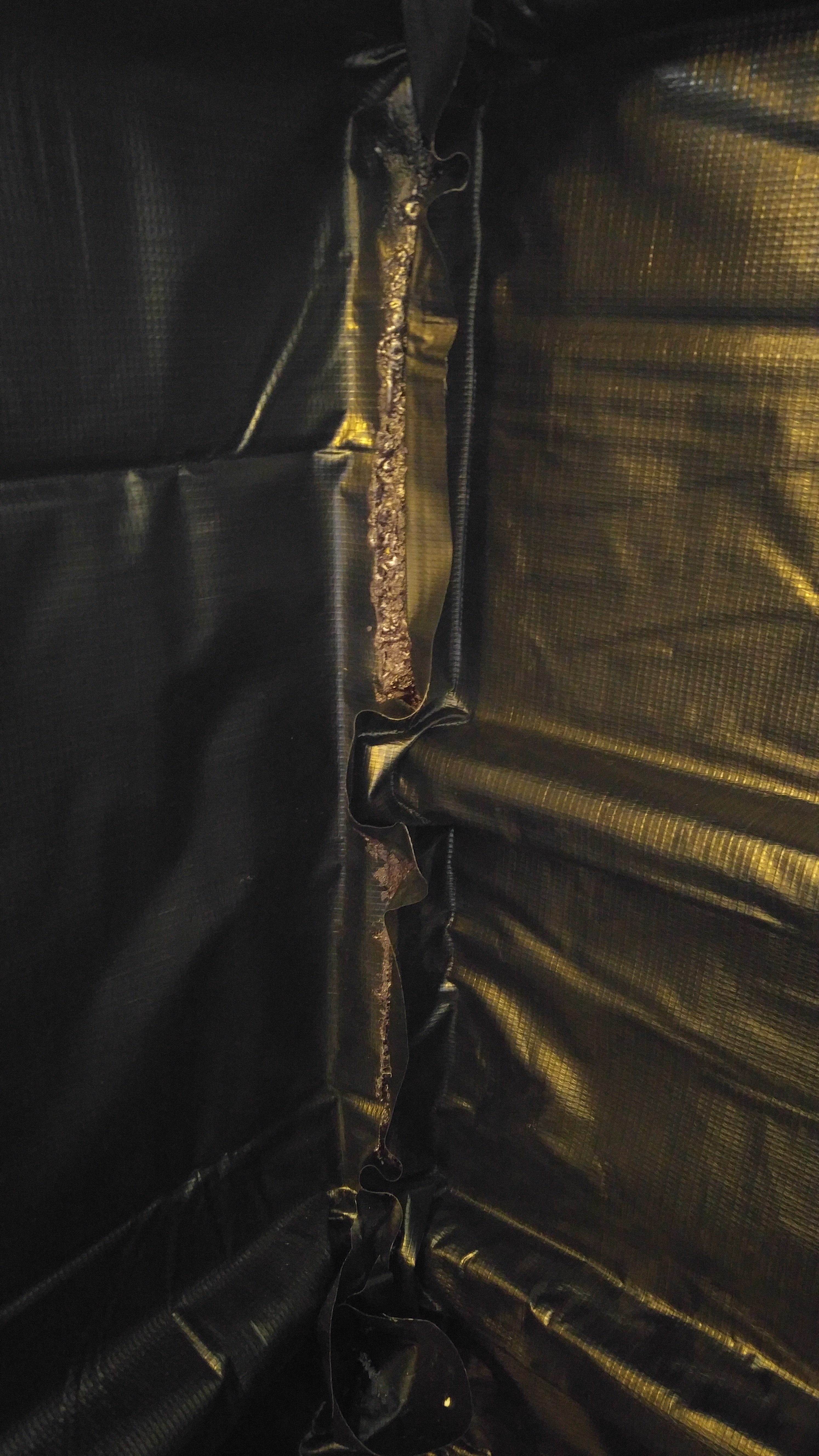
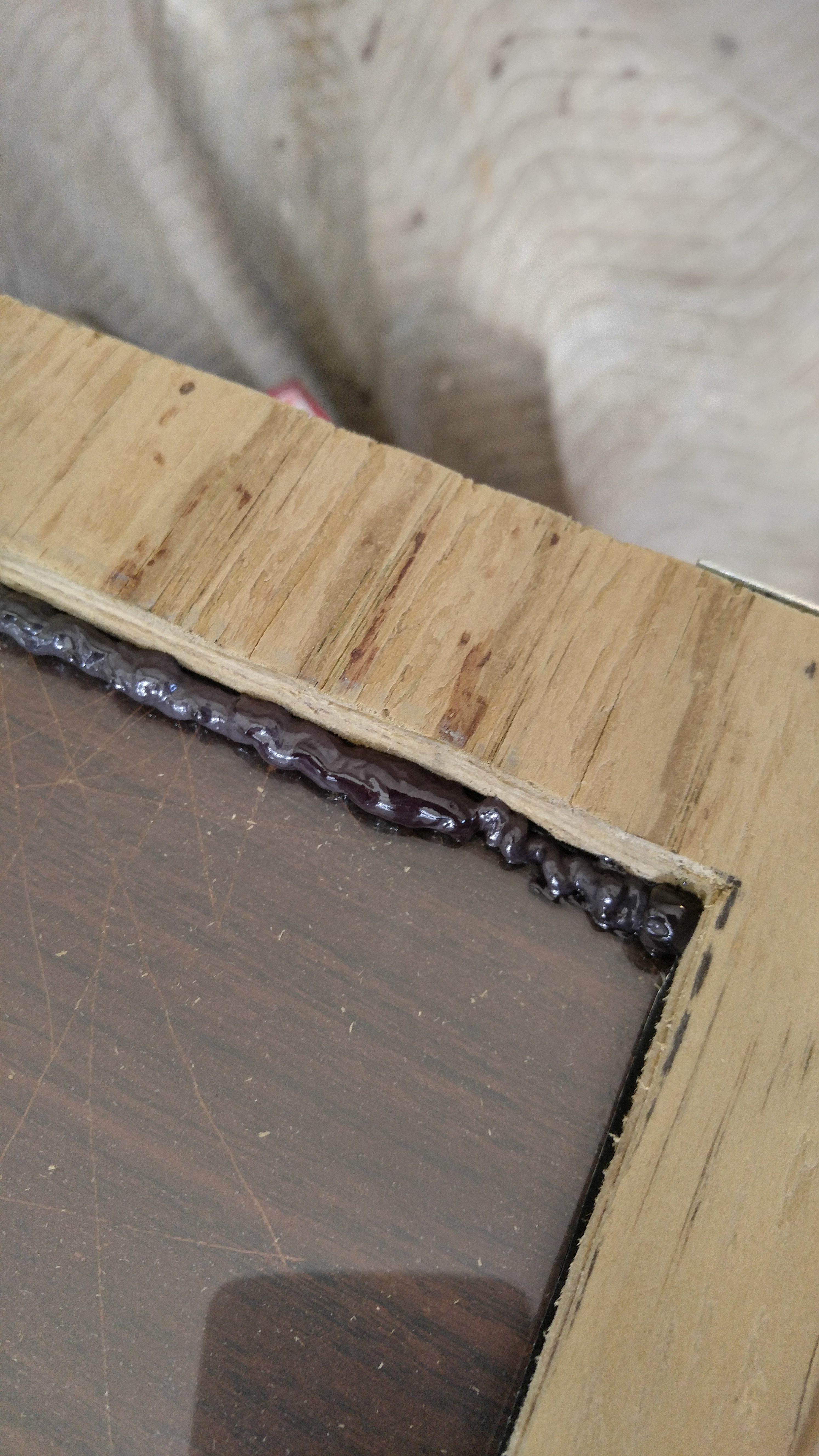
Use waterfall foam along the bottom edge and around the edges of all of the 2″ x 2″ boards on the front wall. This will allow you to flatten the pond liner into the corner, up the wall and around the 2″ x 2″ boards.
You’ll also want to foam the front, top reservoir lip to stick the tarp to it. As I mentioned before, let it dry for a few minutes, flatted the tarp again, and repeat that process a couple times until dry for the best results. You can also cut off excess tarp and/or foam after it is completely dry.
You should now have the entire bottom floor of the grow box covered in the pond liner and it should be foamed in place. It can be a good idea to wait a few minutes after doing this part to give the foam time to set. This ensures that the pond liner won’t slip out of place as you begin to work on new areas.
Again, make sure you smooth out the liner as you work and even take short breaks to give the foam time to dry. Continue all the way up the left wall of the box until the entire thing is covered – just gradually foam an area and then smooth the tarp up to connect.
On the top of the side, there is a 21″ board at the top – you want the pond liner to go all the way up the side of this board but do not foam or connect the tarp to the top of the board (this provides a nice flat surface for the plexiglass top to sit on.
When you have the right wall connected, take a break to give the foam plenty of time to cure. You’ll start cutting the tarp in the next step and could pull it out of place if it isn’t foamed solid.
You’ll need to make a total of six vertical cuts on your pond liner now. Two of these cuts are so the liner can go up around the support beams. The other four cuts will be at the corners to remove large flaps of overlapping tarp.
First begin with corner cuts. Start with the back, left corner. Where you have already attached the tarp to the left wall, go about two inches beyond where you have already connected the liner (should be just past the corner board). At this point, you want to make a cut straight down but stop cutting about two inches above where the reservoir begins. This will leave the left wall covered and the liner will have a loose flap of about two inches at the back corner. Now repeat this same process on the right side.
The only piece of the pond liner that should currently NOT be connected is the center piece that will go up the back wall. However, you have two rows of support beams in your way this time, and the pond liner has large extra pieces on the left and right side still.
Put both of your hands on the bottom of the box and push them to the back wall so your hands are under any pieces of pond liner that are not yet attached. Starting from the bottom center of the back wall, smooth out the liner going left and right. Once you reach the corners, you’ll notice that there is a lot of extra pond liner on both sides.

You should now be left with a sheet of pond liner that is just a bit wider than the back wide of the highland chamber. Before you can start attaching this piece with foam, you need to cut two more vertical lines from the top.

You should now be left with three pieces of tarp for the back wall (all of these are still connected at the bottom and should remain that way). Work with one piece at a time. Foam up the back wall for the area the liner will cover and then smooth it out from the bottom up to attach.
When you wrap around beams, your cuts are based on the center of the beam so that it can cover the entire wall, but you’ll need to make some small horizontal cuts at the beams to get the pieces to lay flat. After you attach the pieces, you can then shoot some foam under the edges at these beams to entire a complete seal.

When you’re done with a sheet, you should see a nice straight line going up the back wall. This is necessary because the next piece will butt right up against it. It is okay to go a bit heavy on the foam at the edges of these sheets to ensure they attach firmly. If you can slightly overlap the sheets, that is best, but you may only be able to get them to sit next to each other in some places (which is okay).

Step #7 – Top & Interior Sealing
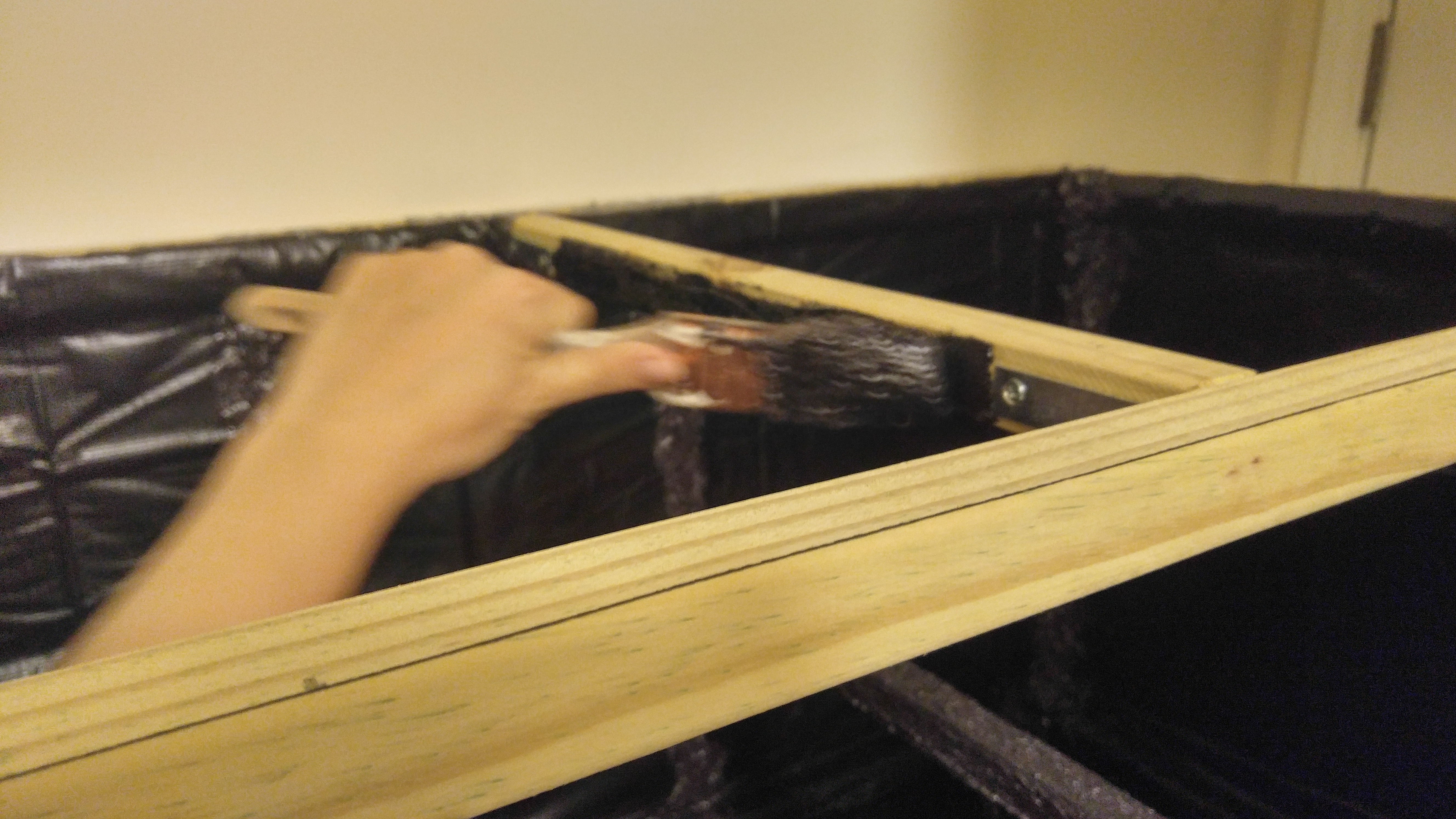
After your foam has completely dried, take another close look at the back wall anywhere you had made cuts previously. If you see any kind of gaps or lose pieces of liner, you’ll want to take care of it now to ensure water isn’t able to get behind the pond liner.
I like to use an old paint brush or even a decent size piece of dried foam. I then spray a bit of foam on it and paint the foam over the joints and gaps. Give it time to dry and the box should be completely sealed on the left, back, right and bottom.
Any pieces of pond liner that might be hanging off the left, top or right of the box can be cut off now. Just try to make sure you make straight cuts here. You may also want to paint a bit of foam on any lose flaps to make sure it’s all stuck in place.
Step Materials
- (1) 4′ x 2′ Thick Plexiglass Sheet
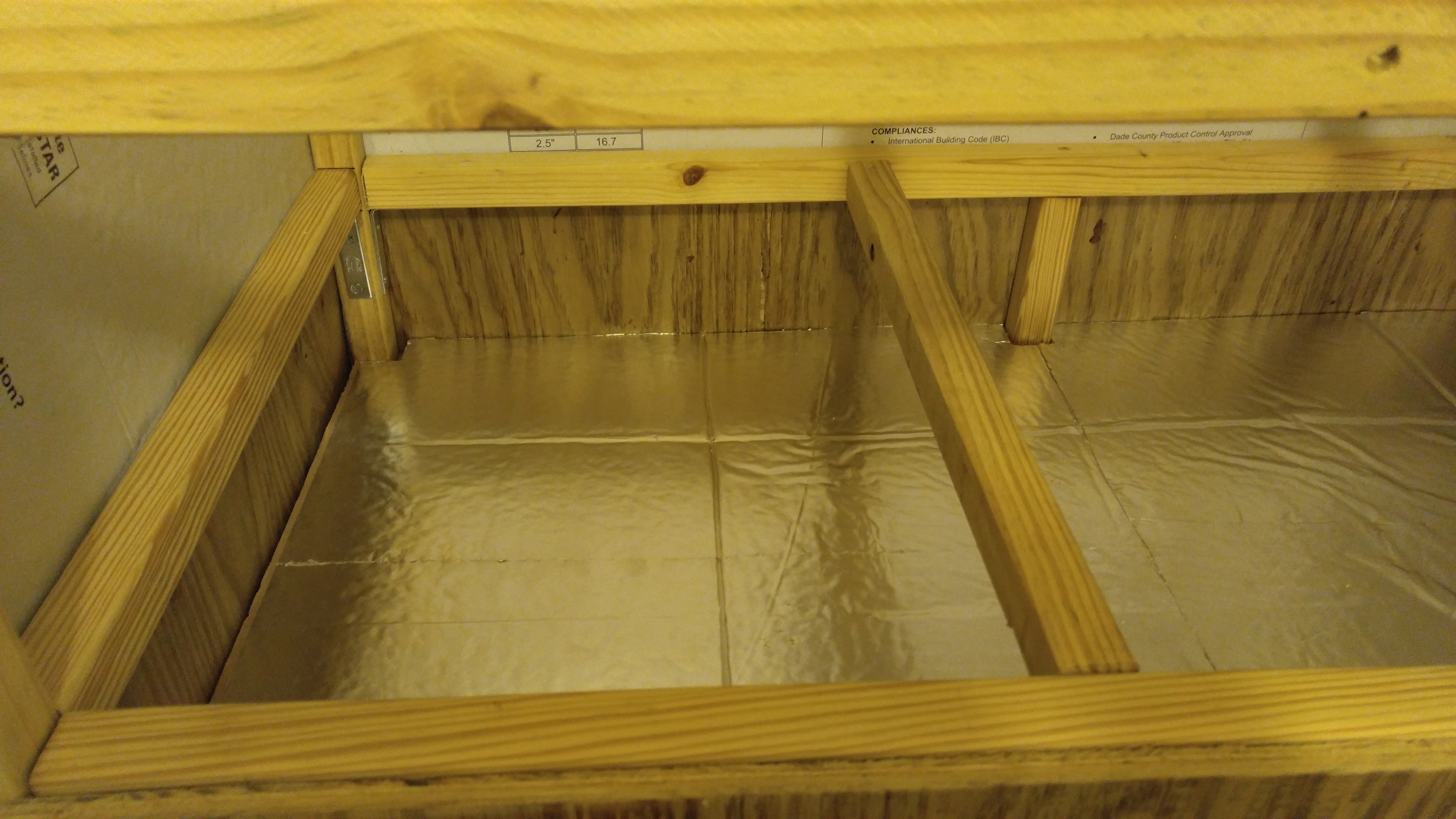
- (1) 2′ x 8′ Mylar Sheet
- (1) 6′ x 18″ Coated Wire Closet Shelving
- (1) 2′ x 4′ White Plastic Egg Crate Panel
- (1) Waterfall Foam Cans
Remember that the foam will expand quite a bit as it dries. For this reason, you want to be painting it on EXTREMELY lightly. Give it time to completely dry and you’ll see it puff up a bit no matter how thin you paint it on. If you go too thick, you’ll big chunks of foam all over the boards and it will take up growing space and/or make shelves not sit right.

Attach these mylar pieces just like you did with the pond liner. Personally, I found it easiest to paint foam on the pond liner where I wanted to apply the mylar, and then stick it to one side and flatten it out across to the other side. Repeat this process for all four of those mylar pieces.
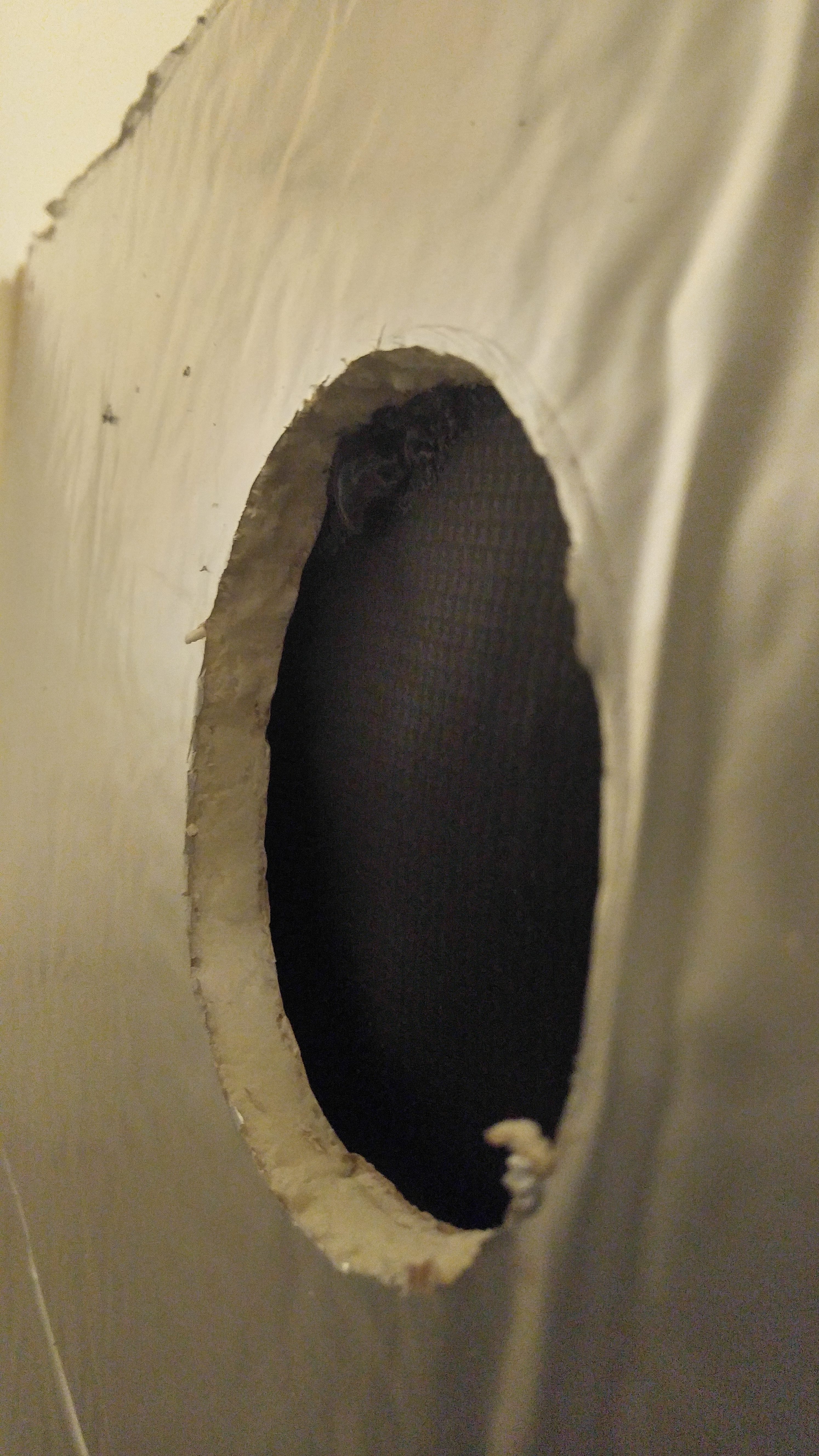
You’re going to need to cut out the pond liner and mylar sheets from all of these holes. I found it easiest to do this with a razor blade. However, be careful with this particular step. You may need to push against the pond liner from the inside to hold the sheet tight to make it easy to cut – this also helps to ensure that you do not separate the tarp from the walls where it has been foamed.
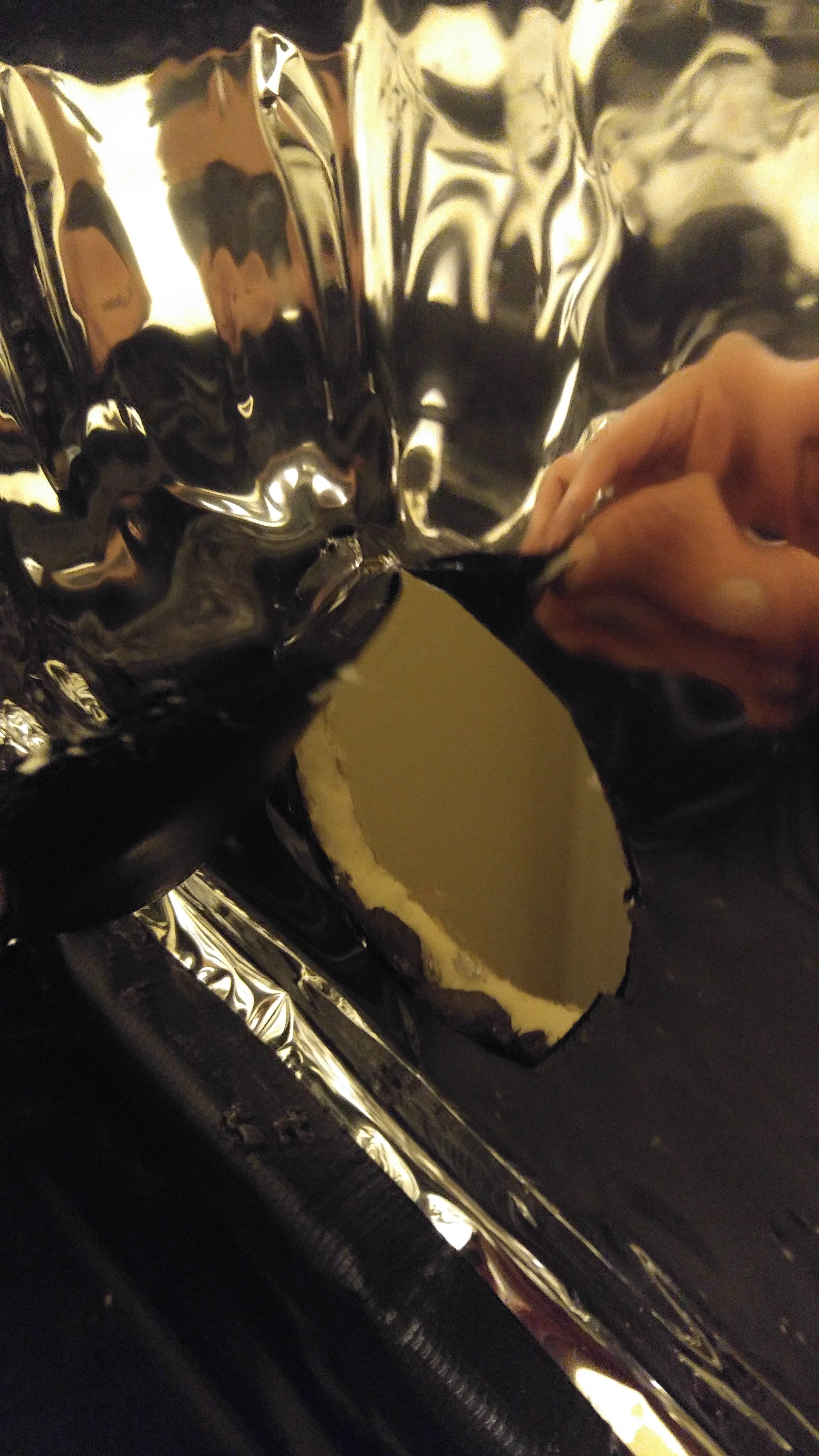
Each of these circular holes that you’ve cut will have a duct tube or vent connected to it. For my chamber, I have two 4″ holes and two 6″ holes. I started with just the 4″ holes and had them connected to the freezer cooling system (see my guide on that system for my reasons why I switched to water cooling). When I switched to water cooling, I added the 6″ holes on the right side – those are connected to the water cooling system and now the 4″ holes are fresh air intake / exhaust when the lights are on.

The duct vent is not entirely necessary though. You could simply have duct tubes attached at each of these openings. However, wherever your cold air will enter your grow chamber, you’ll want something to force the air down. When I used the freezer, the duct vent forced the air down. With the water cooling, I simply have about a foot of duct inside of the chamber that arcs down so that the cold air enters at the very bottom of the chamber at the reservoir (which has ultrasonic humidifier foggers floating there to humidify that air before it reaches plants – this is important because cooled air will be stripped of much of it’s humidity).
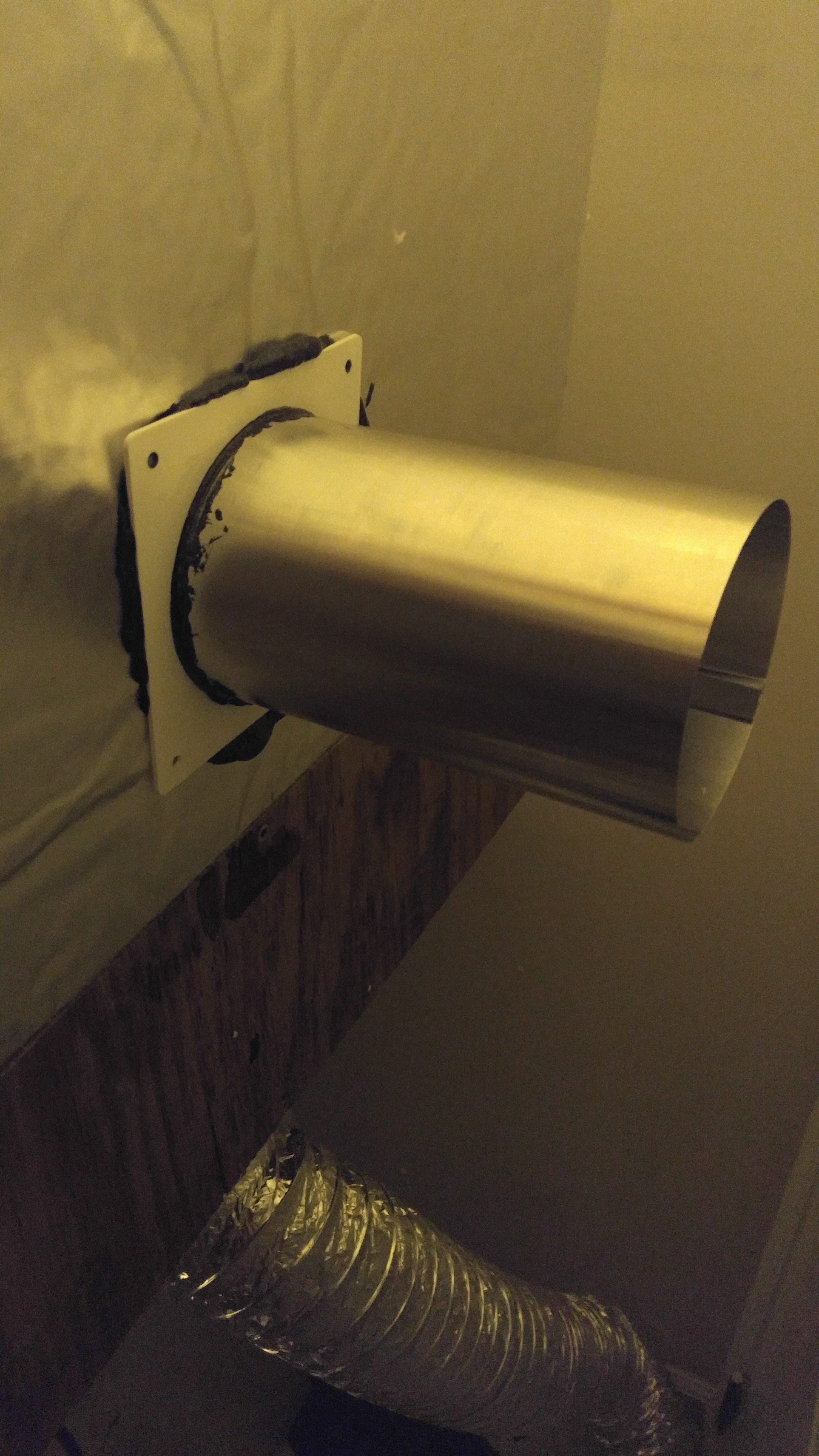
The amount of duct tubing is also worth talking about. The 4″ hole ducts do not need to be very long whether you will use it for fresh air venting or for the freezer cooling system. About 4-5 feet worth on each side is plenty.
The length of the 6″ ducts can depend on what kind of room you have to work with around your chamber. If you’re doing water cooling and will have 6″ ducts, I’d recommend waiting to install these until you read that guide. For my chamber, I used about 5 feet of insulated, flexible 6″ ducting connected to each 6″ chamber hole – this was the length I needed to reach my fan / ice box. However, some designs (especially larger chambers that are 4 feet or taller) could simply use 90° angle 6″ pvc pipes and have them connect directly to the fan / ice box for the water cooling.
Start by putting a small line of waterfall foam all the way around the top of the outside of the frame. Then you simply want to place the plexiglass sheet on top of the chamber – this will squish down that line of foam, sticking the plexiglass in place and also creating a seal.
Give the foam under the plexiglass time to dry. Now inspect the seal around the edge. If needed, you can squirt some foam between the board and the plexiglass on the outside edge of the box, but be sure to go very light if you do this because the foam will expand and you don’t want to get it on more of the plexiglass sheet than needed.
You’re welcome to do this step at any time, but it can be easier to go ahead and add the shelves now. I experimented with a couple of different shelving options for this project.
The simple and very sturdy option is a coated wire closet shelf cut into 24″ pieces (slightly less than 24″ each, 23.5″ – 23.75″, is actually best so that they fit easily without blocking the doors) – PLEASE NOTE – this shelf option ended up rusting a lot, so I later changed it to the egg create shelving mentioned below. However, you may still see some wire shelf pics elsewhere in this guide (they were simply earlier pictures before I changed the shelf). This is what I first started using for the top shelves because I’m mostly going to use this as a seedling and juvenile plant chamber, so I wanted the top to support plenty of weight.

If you put two pieces of wire shelf on the top level, it won’t cover the entire level, but three pieces will be too much. If you have mostly small plants but some taller plants that you want to grow, two wire shelves up top is a good arrangement because this will leave a small area for the taller plants. However, if you want to do all small plants and have a complete top shelf (this is what I’ve done), you’ll need to cut some width off a third piece to get it to fit – this does require a lot of cuts though.
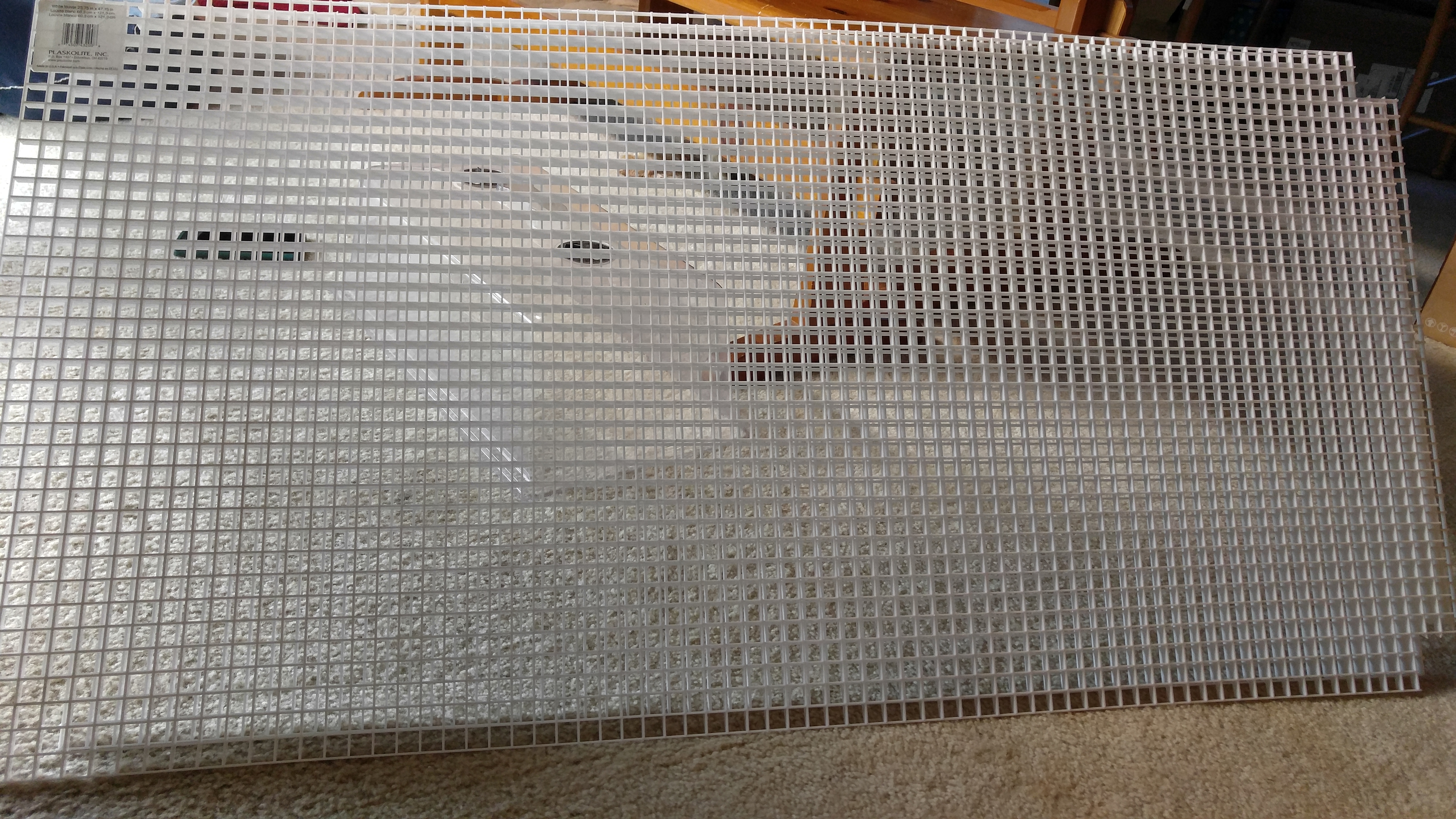
The egg crate is slightly less than 4′ x 2′, the size of my chamber, but my grow chamber has a wood frame inside of it so I have to cut the corners out of the shelf to get it to fit. I removed a 3×3 block section from each corner of the egg-crate (just cut with wire cutters).
If the left / right sides of the shelf seem very flimsy, you may also need to add some waterfall foam to the underside of the shelf on those edges to give some additional support. I my chamber, my fan on the bottom-left actually provides extra support to the shelf above, but on the right side it was flimsy so I had to add some foam under the shelf that attaches it to the right wall of the chamber.
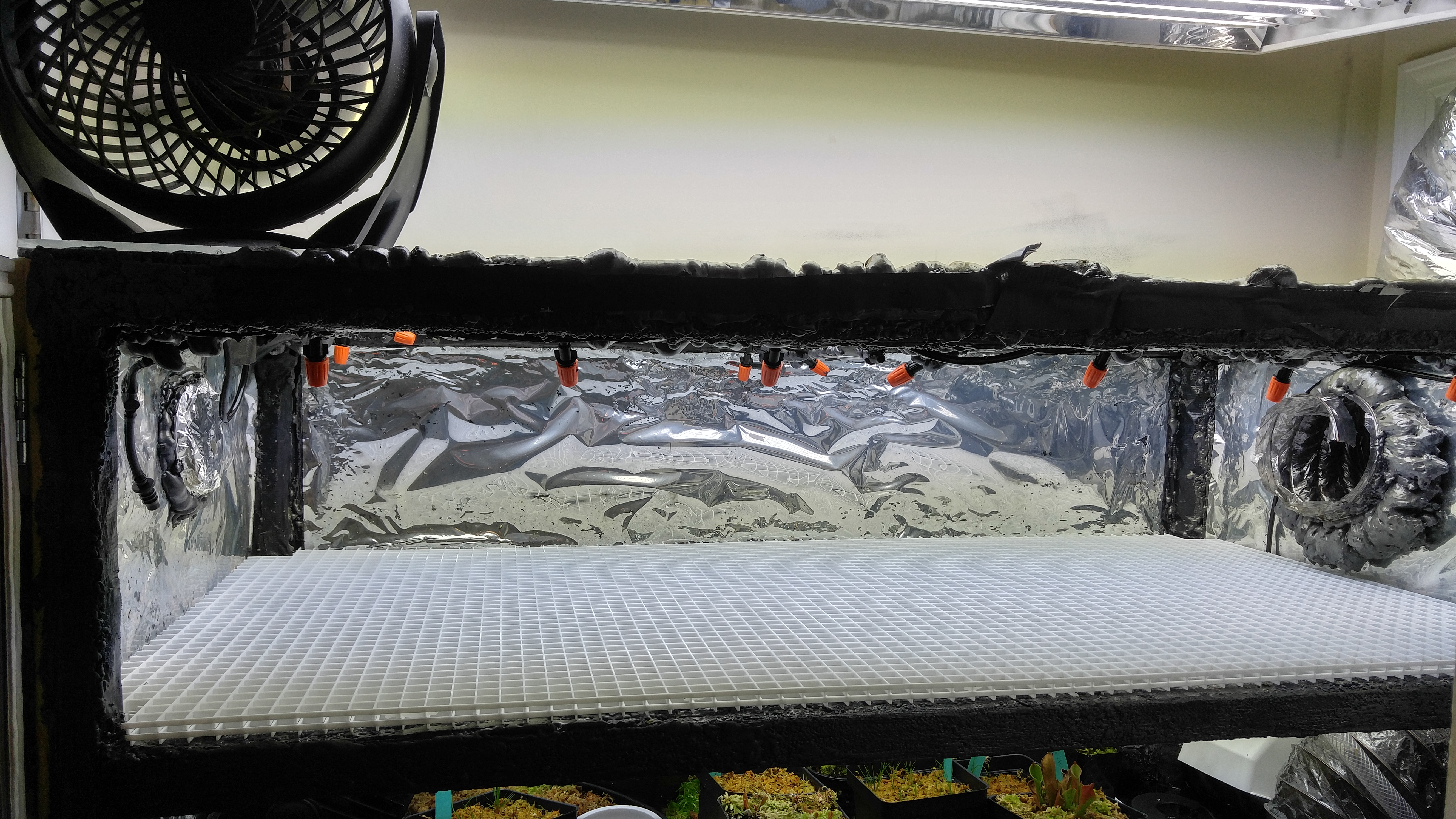
On the bottom level, I have used an egg-crate shelf to cover the left 75% of it. The right 25% or so is left open to give the cooling system air an easy way down to mix with the mist put out by the humidifiers.
To install the egg-crate, you’ll need to cut a 4×4 square (about 2″) out of the left corners – this allows it to fit inside of the box frame on the left side so it can get support by the far left board on the bottom level.
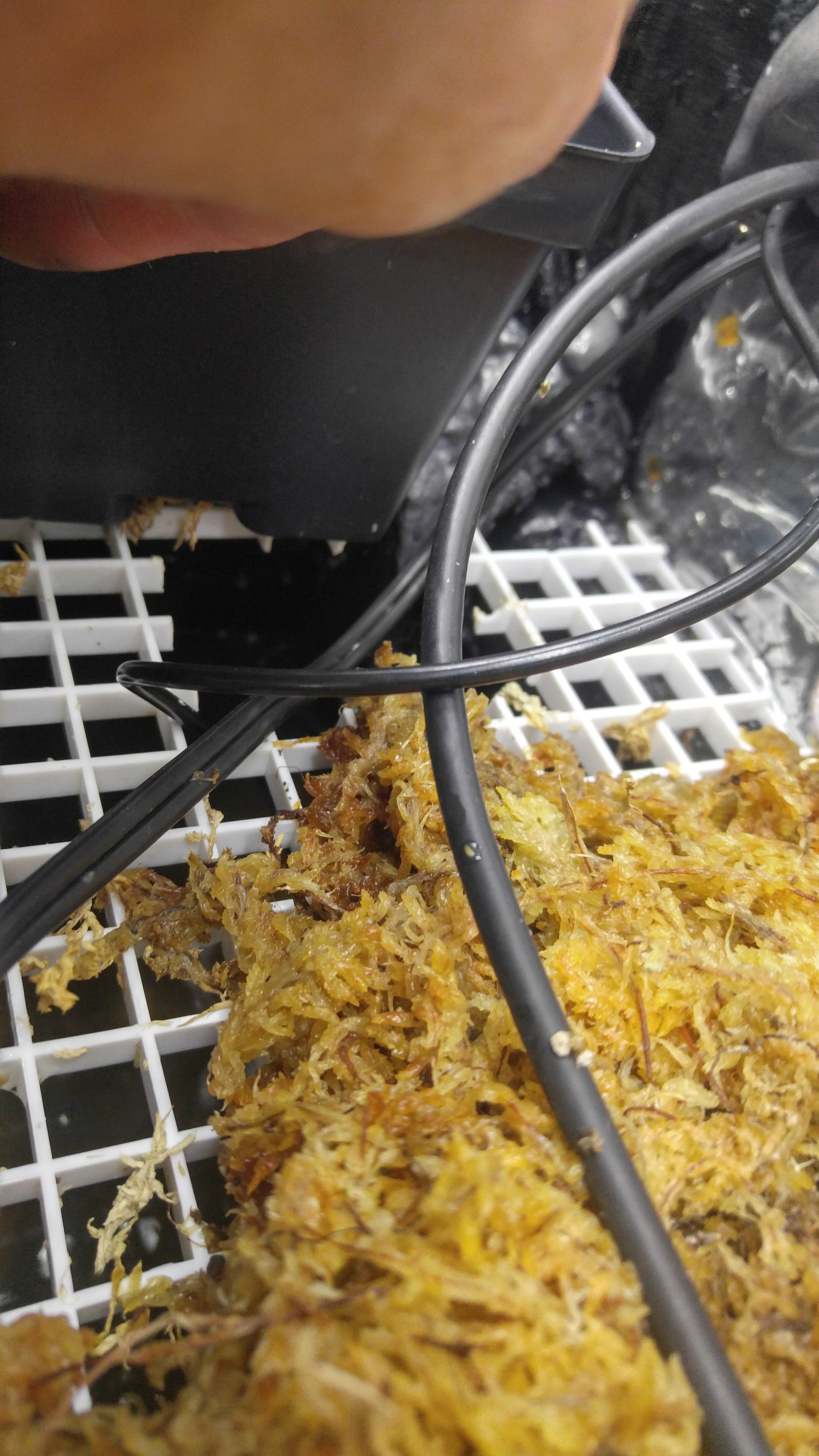
Besides having a large fan on the bottom shelf, I’m also using it to grow live sphagnum moss. Even though my top level is completely covered in pots, I don’t have them in trays (and they are mostly circular pots), so enough light gets through to the bottom level to allow the moss to grow. The main downside to doing this is that is raises humidity in the chamber even more and makes it require external venting and fresh air during the day to keep humidity below 90% (this is the purpose of my 4″ ducts after I switched to the water cooling method instead of the freezer). If you’re going for a completely sealed system, consider leaving out the sphagnum moss layer to help keep humidity below 90% during the day.
You may also notice that the sphagnum moss on the bottom level doesn’t go all the way up to the edge of the egg-crate shelf, especially on the front and right sides. With my automated watering system, the moss bed receives a rain shower every two days for about 10 minutes. If the moss went all the way to the front edge, it could possibly end up leaking water out of the doors. For this reason, I pulled the moss back a couple of inches from the front edge so I can see the water reservoir through that area of the shelf – this ensures that all water going into the moss will drip down into the reservoir and not onto the front lip of the chamber (water on that lip can simply roll out of the chamber, so it is the one place you need to make sure water can’t get to).
Step #8 – Door Construction & Installation
The last construction step to build the grow box is to create the doors and attach them. I used two plywood sheets for my doors, although I believe another type of wood would’ve been better to try to prevent them from warping (perhaps a type of cabinet wood would be better).
- (2) Metal Corner Brackets (could use 2 more bolt locks instead)
- (4) Metal Door Hinges
- (1) Metal Slide Bolt Lock
- (1) 18″ x 24″ Thin Plexiglass Sheets
- (1) Waterfall Pond Foam Can
The first thing you want to do for the doors is to line the side that will be on the inside of the chamber. Just like I did in the box itself, I lined the doors with the pond liner tarp and then with mylar. These are best applied using the painting method with the waterfall foam so you keep a thin layer.
I used a 18″ x 24″ thin plexiglass sheet for the window, so it wasn’t large enough to cover the entire door. The hole I cut out was about 3-4″ smaller than the plexiglass. I then foamed around the edge of the hole and placed the plexiglass on top of foam to seal it in place. I also flipped it over and put a small amount of foam along the inner edge of the hole. You’ll at least need a sheet on the inside of the chamber, but I also put a second sheet on the outside to make it a double paned window for extra insulating power. For the second sheet, I just foamed around the edge of the hole and then placed the sheet on top to seal.
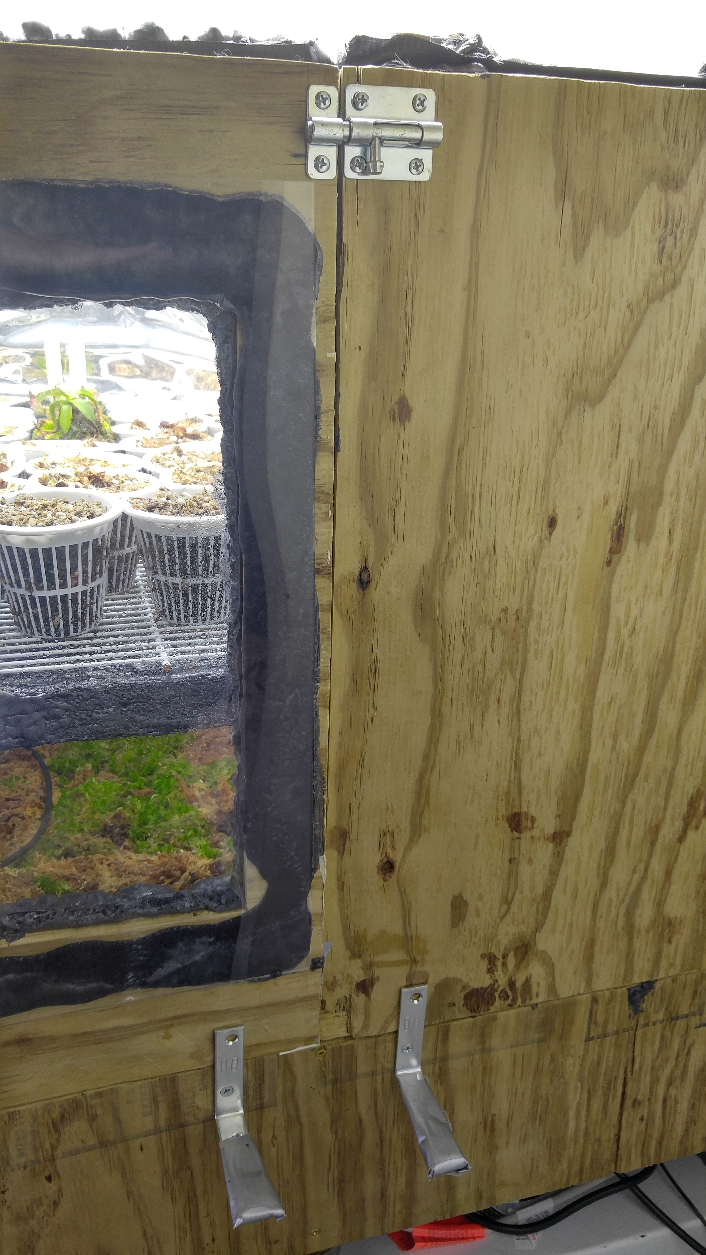
With both doors in place, install latches to the front that will help keep the doors closed tight. I put a sliding bolt lock on the top. I could’ve used the same on the bottom but just used what I had handy, which was two more corner brackets. I just screwed them into the plywood below the doors with one screw for each bracket so I could rotate the bracket to hold the doors closed. The edges of these can be a bit sharp, so I wrapped them in duct tape too, lol (this would best be done with two more locking mechanisms from the hardware store though – something that would function good installed vertically).
Congrats.. The construction of your highland Nepenthes grow chamber is now complete! To get it running, you now just need to hook up electronics that will control the environment.
» Electrical Equipment for Highland Nepenthes
It’s now time to add your electrical components and your grow chamber will be finished.
Please Note: This section covers the general electrical equipment used, but it does NOT include the cooling system or watering system! Please see the additional guides for these systems for the required supplies and instructions to build and install them.
Most of the equipment used here is best purchased online (I recommend Amazon). For the products that I recommend to buy online, they’ll be linked to the relevant Amazon product page in the list below. Most of those products are specialty goods and are hard or impossible to find in local retail stores – even if you can find them locally, they’ll likely be significantly cheaper online. For everything else, I’ve indicated in the list below where to buy them.
Electrical Supplies
- (1) Inkbird ITC-310T Temp Controller or Sentinel DEC-4 Environmental Controller (Only Use Sentinel If Censor Can Be Kept Dry)
- (1) SensorPush Environment Tracker for Phone (Optional but useful)
- (1) SunBlaze 4′ T5 Lighting w/8 Bulbs
- (1) Set Grow Light Pulley Ratchet Hangers (Includes 2 in Set)
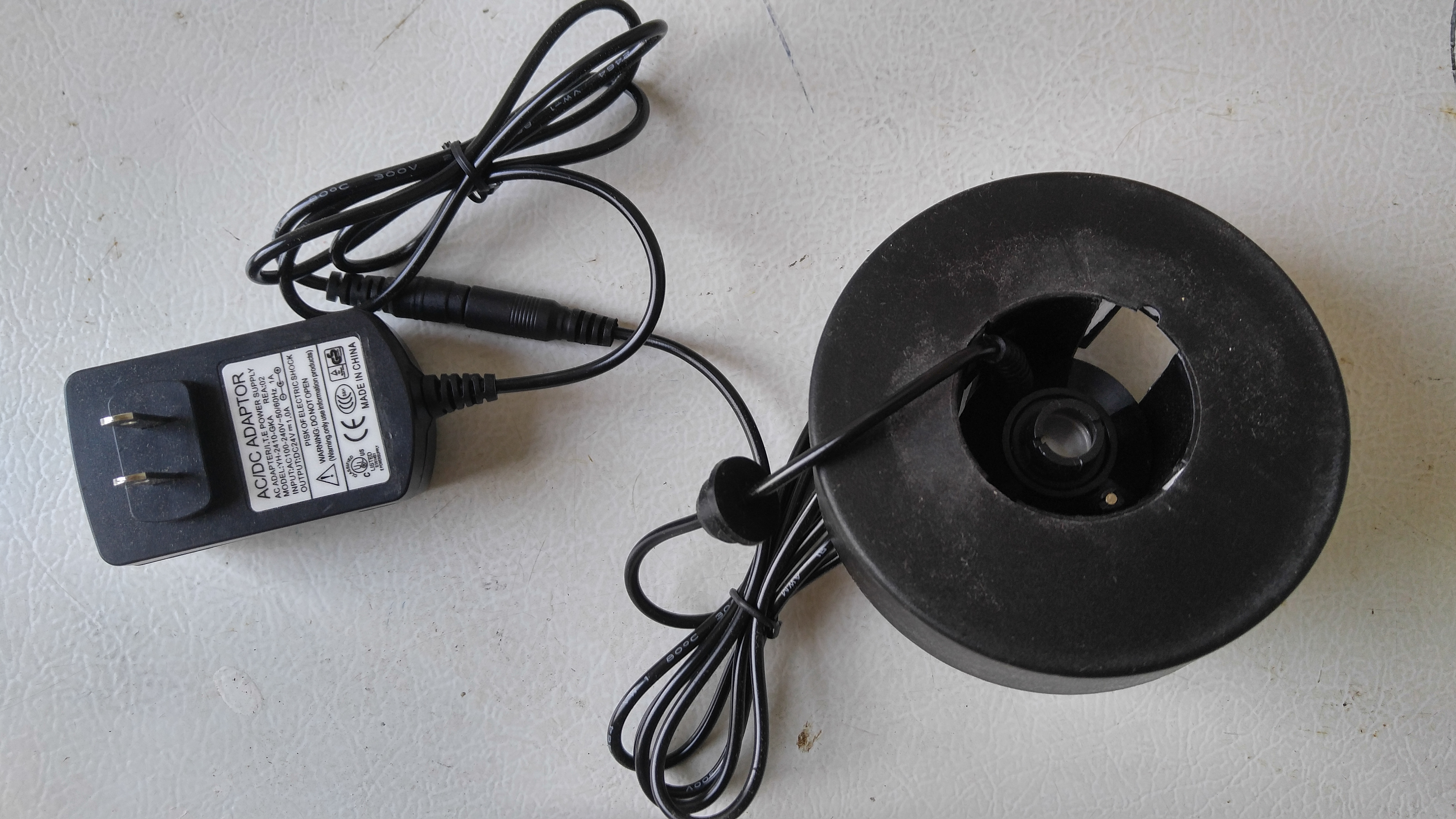
- (3) AGPtEK Mist Maker Ultrasonic Humidifiers
- (3) Mist Maker Floats
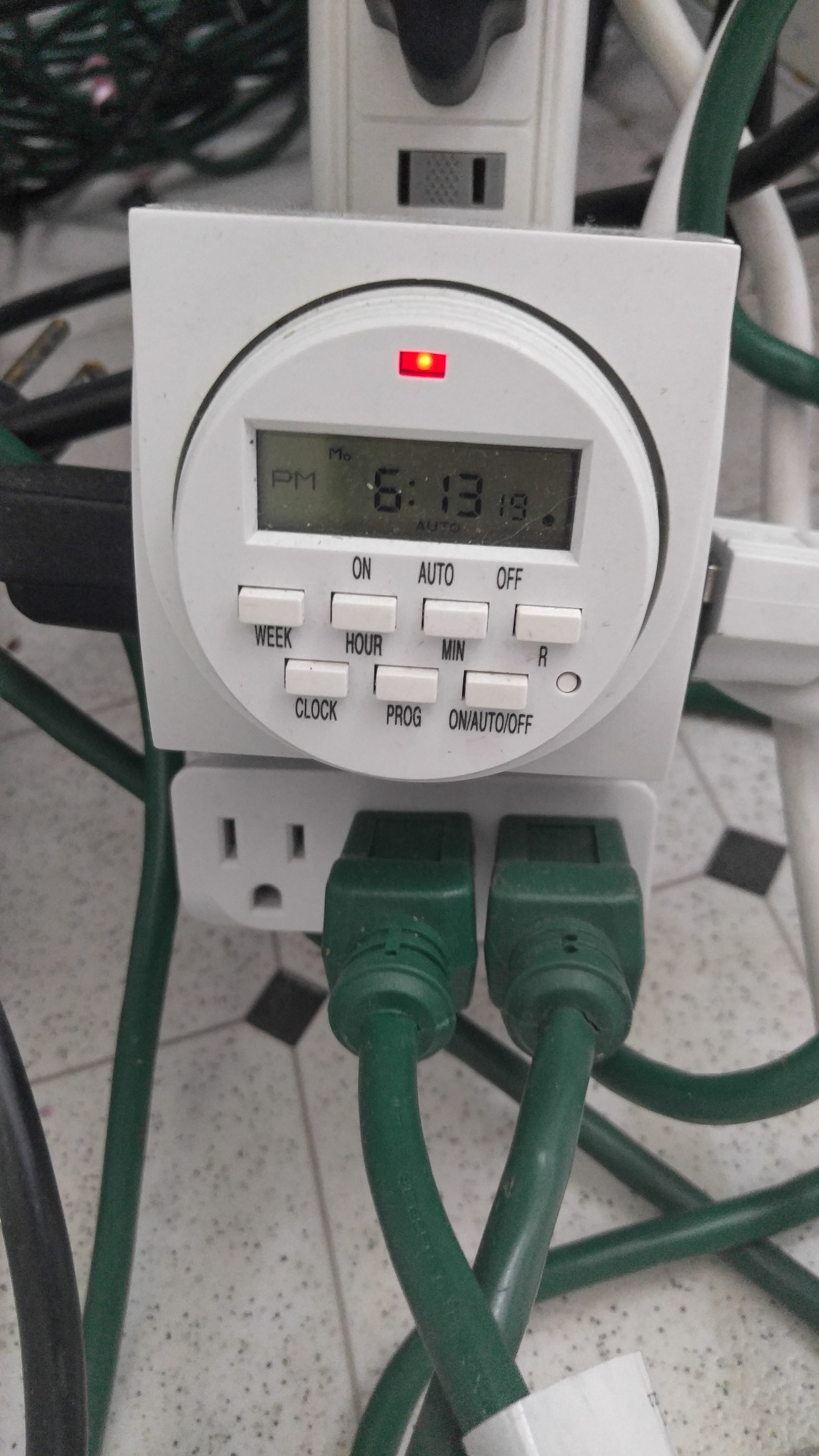
- (1) HydroFarm 7-Day Digital Timer – Will need a second for automatic watering system.
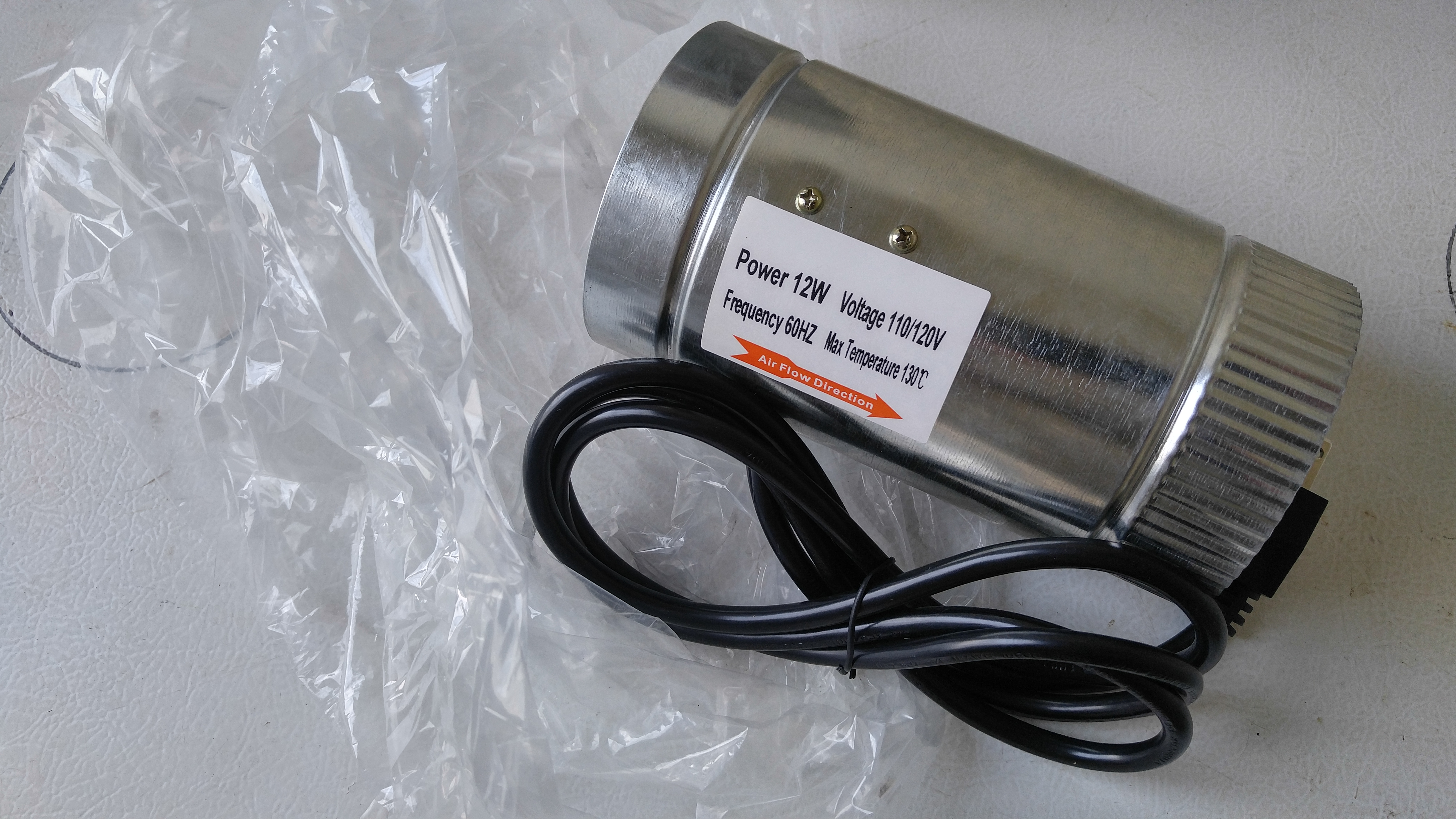
- (2) 4″ Inline Duct Fans – See notes below about these; you may only need one.
- (1) Apollo Horticulture 4″ Inline Duct Fan – Use one of these instead of the other 4″ inline fans for more power and adjustable speed. Useful for fresh air venting to control day humidity levels.
- (3) 10″ Fans (Lowes or Wal-Mart)
- (2) Long Metal Shelf Brackets & Screws (Lowes or Wal-Mart)
- (1) Waterfall Pond Foam Can (Lowes)
- (4) 6-Socket Surge Protectors (Lowes or Wal-mart – Some used with cooling / watering systems)
- (3) 10-Feet Extension Cords (Lowes or Wal-mart – Some used with cooling / watering systems)
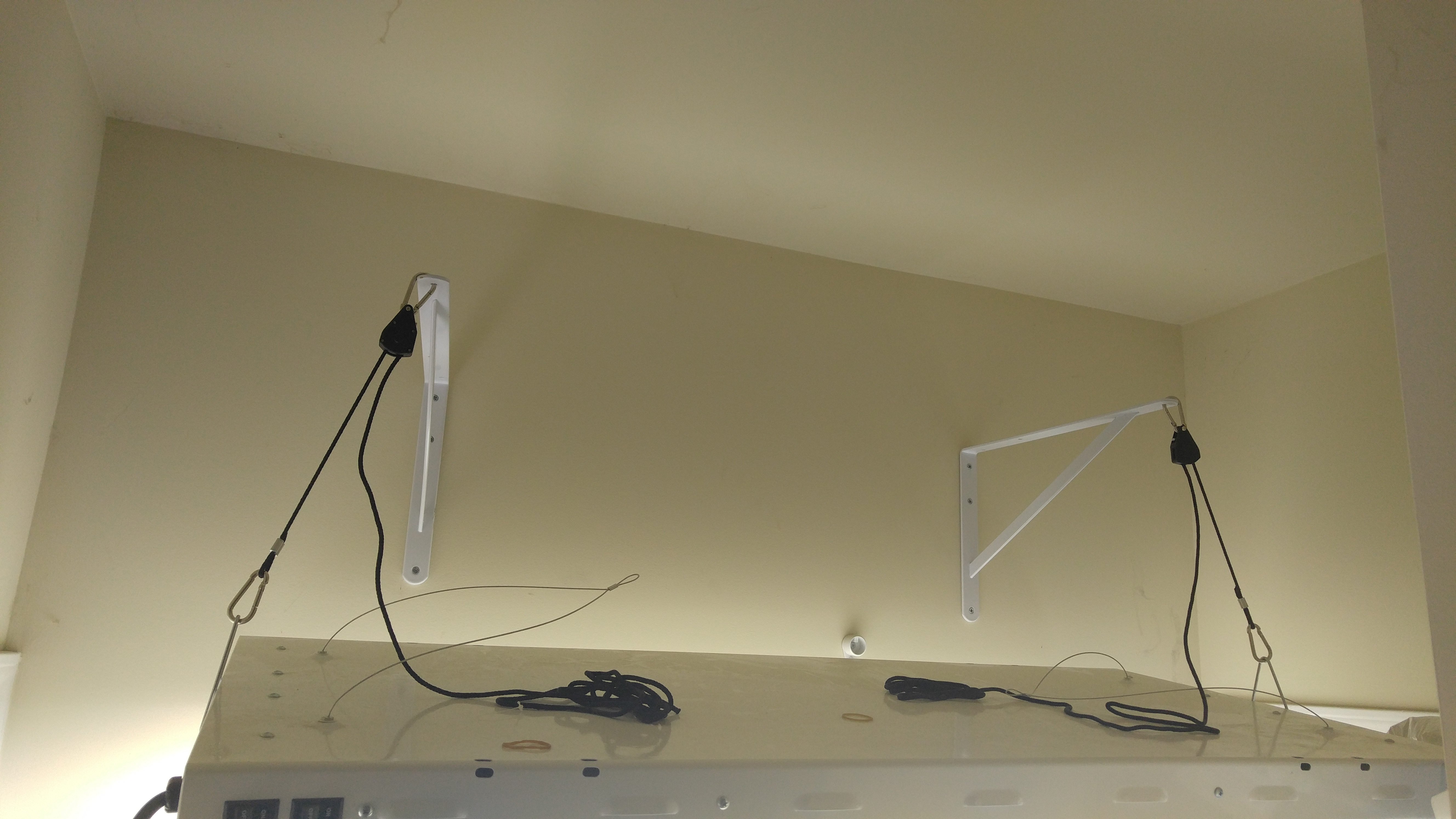
To fix the heat issue, I mounted the T5 lights to the wall behind the chamber. Actual mounts sold for these lights are very expensive ($100+). I made my own using metal shelf brackets and pulleys that cost a fraction of that.
The metal shelf brackets should be as long as possible so they stretch out over the grow box at least half way. It’s important to mount these into the wall studs, even though it may not be the exact spacing you would like for the lights. Use large screws to attach these into the wall.
My lights are about 10-12″ above the top of the plexiglass. My top shelf plants receive about 15,000 – 25,000 lux of light intensity (higher levels are in the center). This is quite high, but the plants seem to love it. However, if you can’t reach these light levels, don’t worry about it as long as you can get at least 8,000 – 10,000 lux. What is lux? It is the level of light intensity measured at the top of the plant height to accurately gauge how much light they receive. You can download simple, free apps on your call phone to measure your lux levels – try an app called Light-o-Meter, for example. Cell phone measurements may not be 100% accurate, but they are a good indication and can be compared to outdoor levels too (full sun, midday can give 50,000 – 100,000 lux).
The lights then connect to the timer to automatically turn them on and off each day. I run mine on a 14 hour on and 10 hour off cycle. Try to set your time so that it won’t be light outside when the chamber lights are on – you can actually get some supplemental natural light in through the top if you have it near a window.
These two holes can now be used to run your electrical cords outside of the box to connect them. This keeps your electrical connections outside of the box and away from water. When you are completely done with them, you can seal them up using waterfall foam. However, do not be in any hurry to do this because you may have other things to run through these holes later (for example, if you will be connecting an automated watering system, the front-right hole will be used to run two 1/2″ water tubes).
On the left, I have put a 10″ fan on high power and pointed it at the left wall but arched slightly up. The power cord for this goes out the back-left hole and it is plugged in to run 24/7. This creates a recirculating wind current in the box that circulates up, across the top to the right and back down. You could choose to put a fan on the top level, but it would take away from growing space, although you could use a smaller fan on the top.
In the picture above, you can see a black cord connecting to a small silver device on the left. That is the sensor for the Sentinel digital environment controller. The controller box stays outside of the chamber, while that sensor goes through the back-left hole that you cut. I like to hang mine from the underside of the wire shelving. Whenever you choose to put this sensor, it won’t make a huge difference, but you do want to keep it from getting directly wet and you also want it to have decent air flow (so I put mine near the fan). Since I have a watering system, I put a small piece of black tarp on the shelf directly above the sensor so that falling water rolls away from it and not on it.
*SENTINEL DEC UPDATE* – With my automated watering system, it ended up being too much for the Sentinel sensor after enough time passed. It lasted for close to two years, but for the price that isn’t that great. I do still believe that this controller could work, but I believe for long-term use with a watering system you would need a larger chamber with some dry areas or a dedicated duct that recirculates chamber air over the sensor and back into the box. If you can’t protect that sensor from water, get this instead – Inkbird ITC-310T Temp Controller. It won’t control humidity but it is waterproof. Ultimately, there isn’t anything to control humidity that is waterproof. My grow box design keeps high humidity without a controller, so I just don’t use one and run humidifiers at night to counteract the AC. All Sentinel info from my original build can still be found in this article, so keep this update note in mind.
The new Inkbird controller that I’m using has a nice advantage over the Sentinel besides being waterproof – it can have multiple temp settings in a single day, so you can gradually lower night temps. I basically drop the temp 5-10 degrees each hour until I get to my target temp for the night. Otherwise, my cooling system will usually be too powerful and drop it 25+ degrees in a single hour.
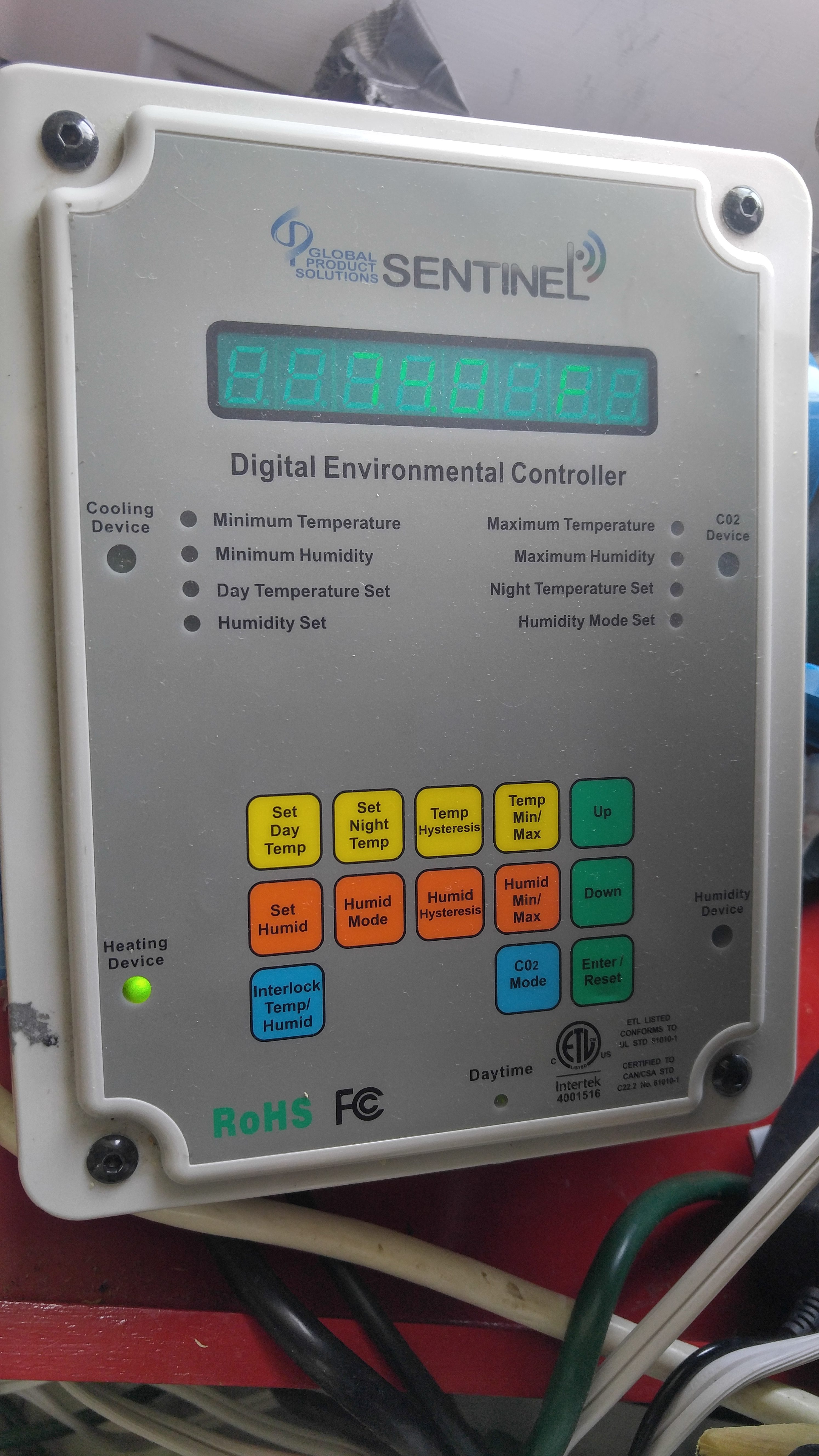
The main goal of using the Sentinel DEC-4 is to control the temperature and humidity levels of the chamber to keep steady highland conditions. I went for this particular device because of the conditions I wanted to achieve – different temperature and humidity levels based on whether it was day or nighttime). I set temp / humidity for the day and temp / humidity for the night, and the box cycles electronics on and off to maintain those levels.
It can accommodate a cooling device and a separate heating device to control the temperature. I just use the cooling feature right now, but if I put this box in the garage and needed winter heating then I would simply connect the heater to the heating socket. For humidity, it can either go up or down. Since I want fairly high humidity at all times, I use this socket to raise humidity to my set level (but it could be reversed and run exhaust fans to drop humidity to set levels).
For mine, I just have the surge protector for the cooling system connected to the cooling socket, and I have two ultrasonic humidifiers connected to the humidity socket (a third fogger is connected to run whenever the cooling system is running). I do not currently use the heating socket or the CO2 socket. The CO2 feature won’t detect air levels – it can simply be configured to run at night or day or when specific devices are off. To get full CO2 detection and control, you would have to go for the Sentinel CHHC-4i, which is about twice the cost and likely isn’t necessary for Nepenthes.
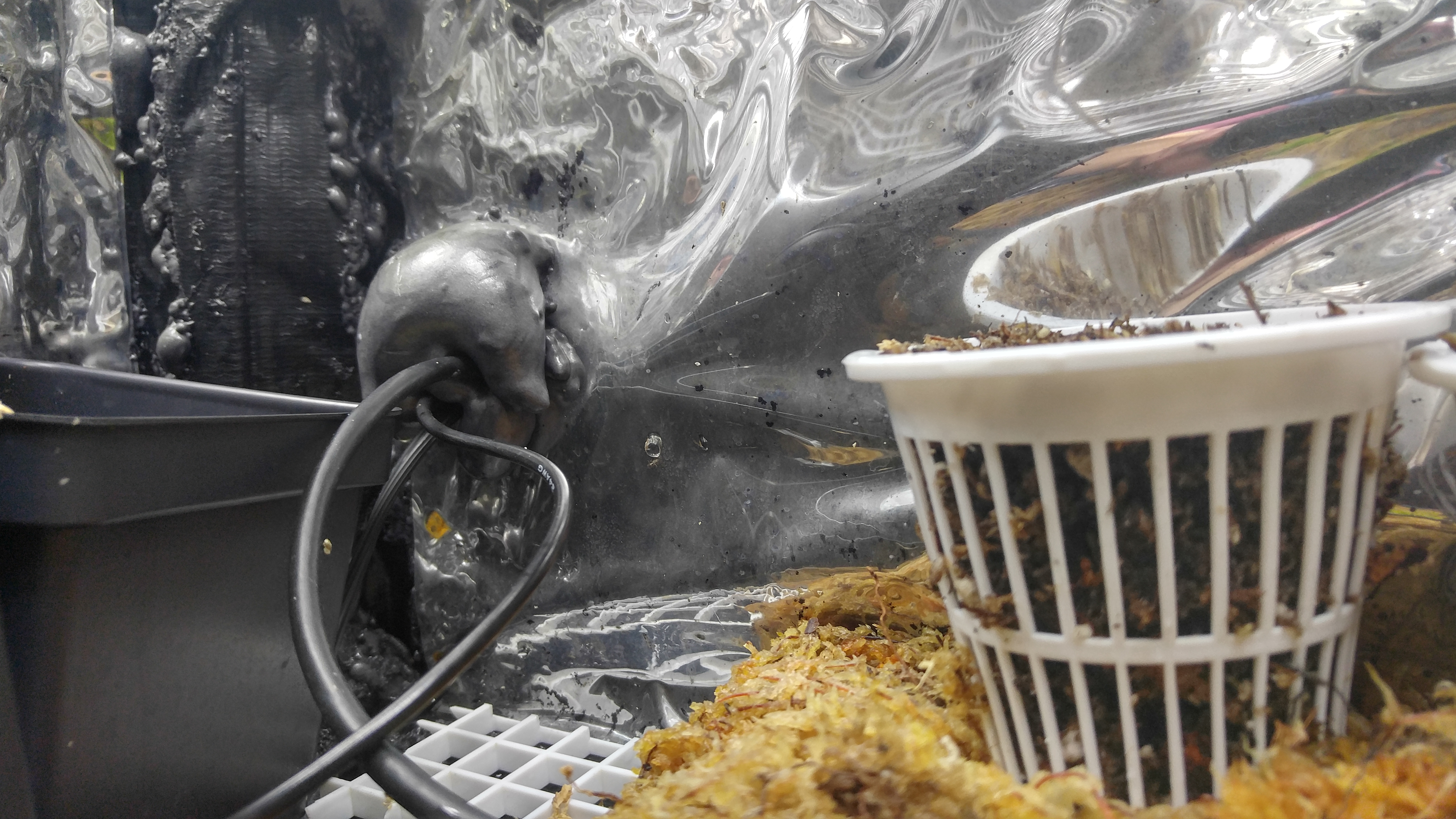
For my foggers and floats, they actually sat too high in the water. Try connecting the fogger with it in the float and place it in a filled reservoir. If it doesn’t put out mist or puts out very little, try gently pushing the ring down slowly to figure out the optimal water depth for the most fog output. Note: Be careful not to touch the water spout coming out of the fogger or the water inside of the ring – it almost shocks you, I assume because it is vibrating so fast.
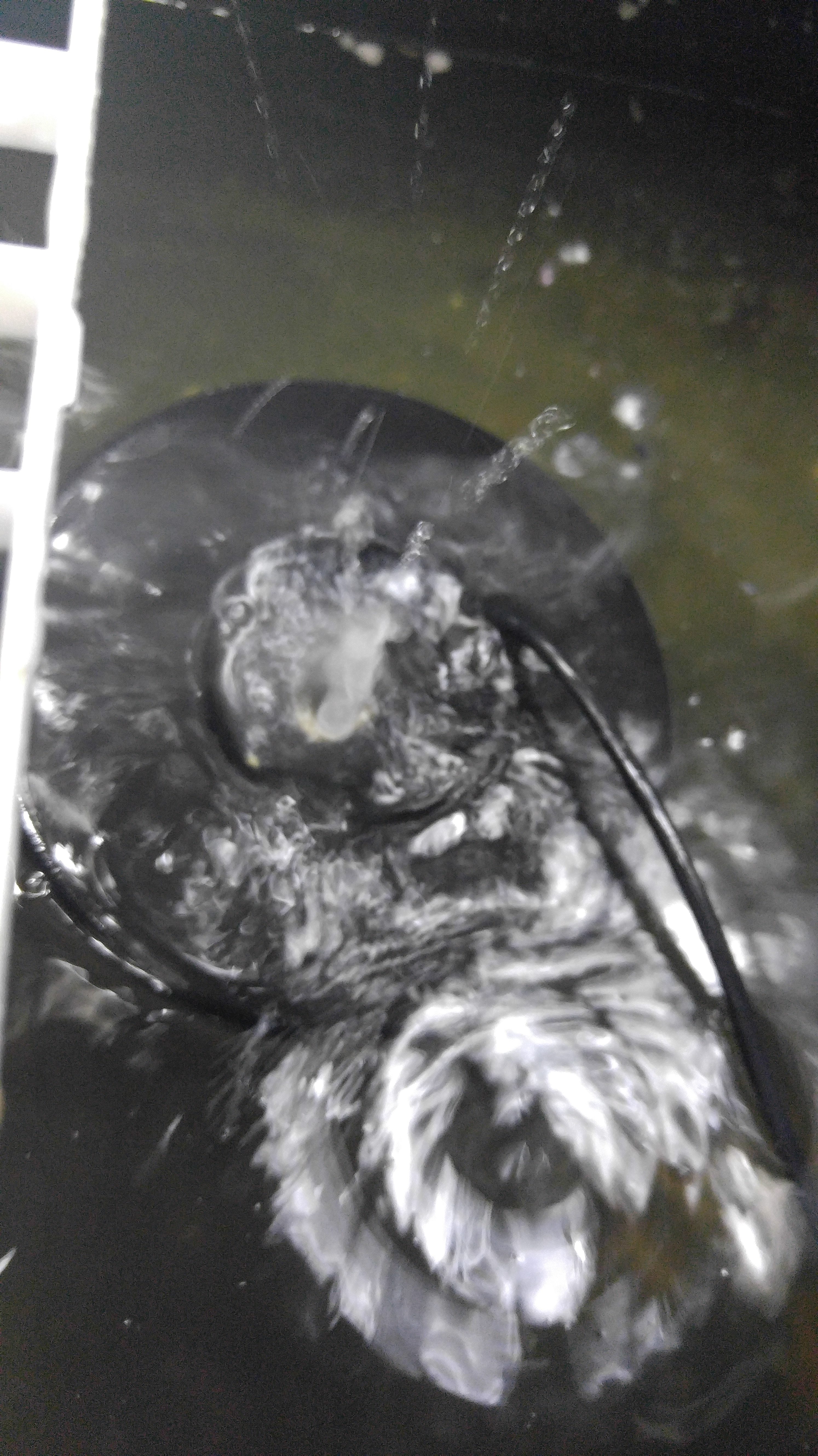
I set up one fogger on the left side of the grow chamber and two more on the right. When humidity gets low, the Sentinel DEC turns on the left fogger and one of the right foggers. The other right fogger sits below the cold air output duct and runs anytime the cooling system runs. Put the fogger in the float and place it in the water reservoir. The cord then connects to the plug with a connector – you want that connector outside of the grow box, so feed the cord through one of the cut cord holes on the left or right, depending on which side the fogger is going to be located.
I just cut a hole in the back of the bottom shelf to easily add the fogger and also to be able to get it out and replace it in the future. Try to place this hole where it won’t cause the shelf to become unstable – the hole should be large enough for the ultrasonic humidifier to fit through (not the float though – that can just stay in the reservoir).
I had to lift the back corner of the shelf to add the float. Then I dropped the fogger down the hole into the float. The cord for the fogger then goes out the hole in the back wall.
After switching to water cooling, which used new 6″ duct holes that I added, I disconnected the inline fans from the freezer and simply had these fans running during the day to vent fresh air and to reduce humidity to reasonable but still high levels (down to 80% or so). After adding a bed of live sphagnum moss to the lower level of my chamber, it made day humidity levels too high, even with these vent fans running. For this reason, I ended up adding a larger fan to the intake duct and removed the inline 4″ fan on that side (this is the side blowing in fresh air).
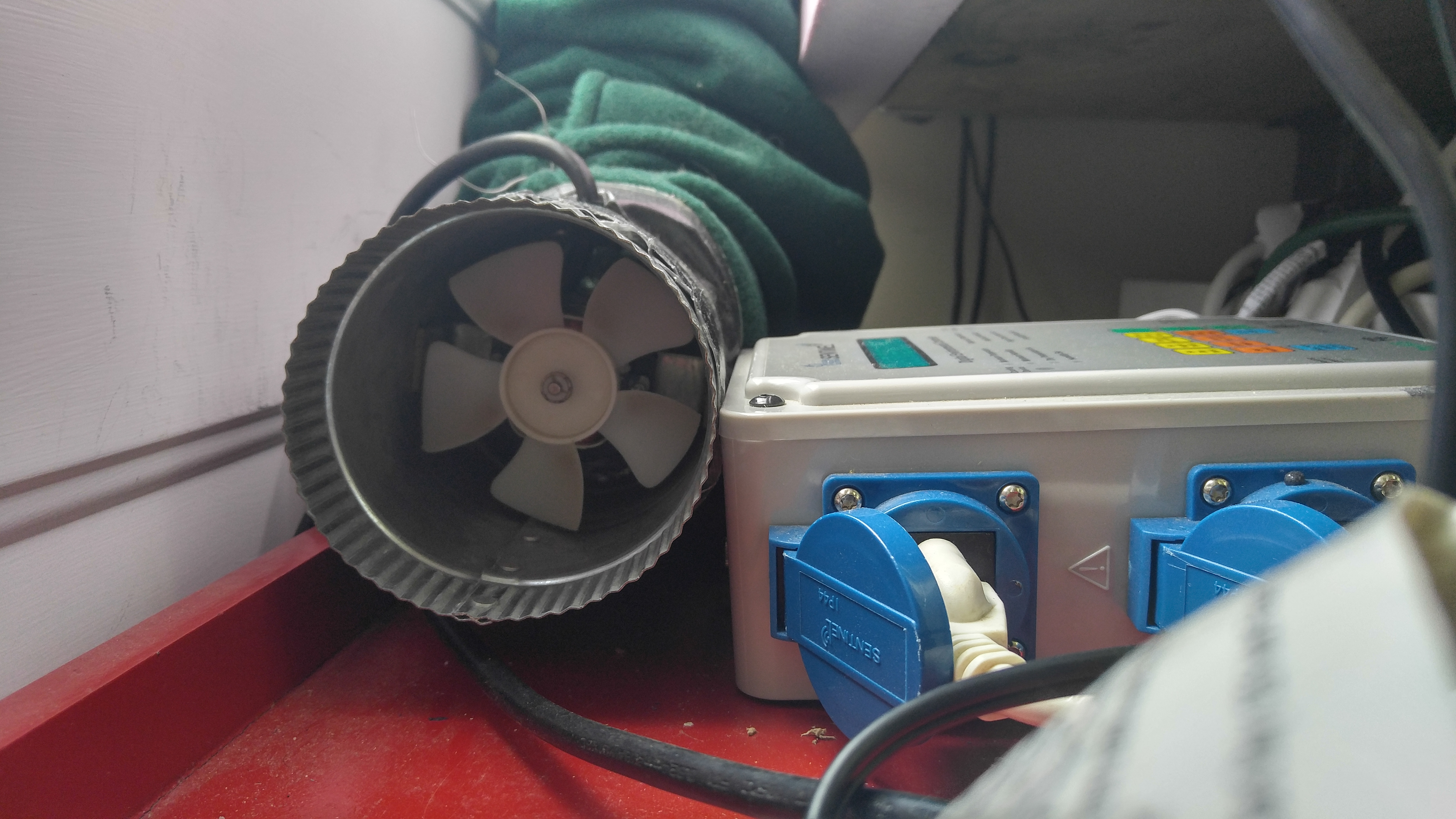
This second kind of 4″ inline fan, the Apollo Horticulture, has almost twice the air flow power and a variable speed controller so you will be able to dial it in to achieve the day humidity levels you want.
Out of everything that I have mentioned and recommended here, that 4″ Apollo Horticulture inline fan is the one thing that I have not actually purchased and used… yet. I will very likely end up buying that exact same fan and hooking it up as I have recommended for you. However, as of this moment I have not yet done that one part. Instead, I have taken one of the 10″ fans and converted it to connect to the intake side of the 4″ duct exhaust.
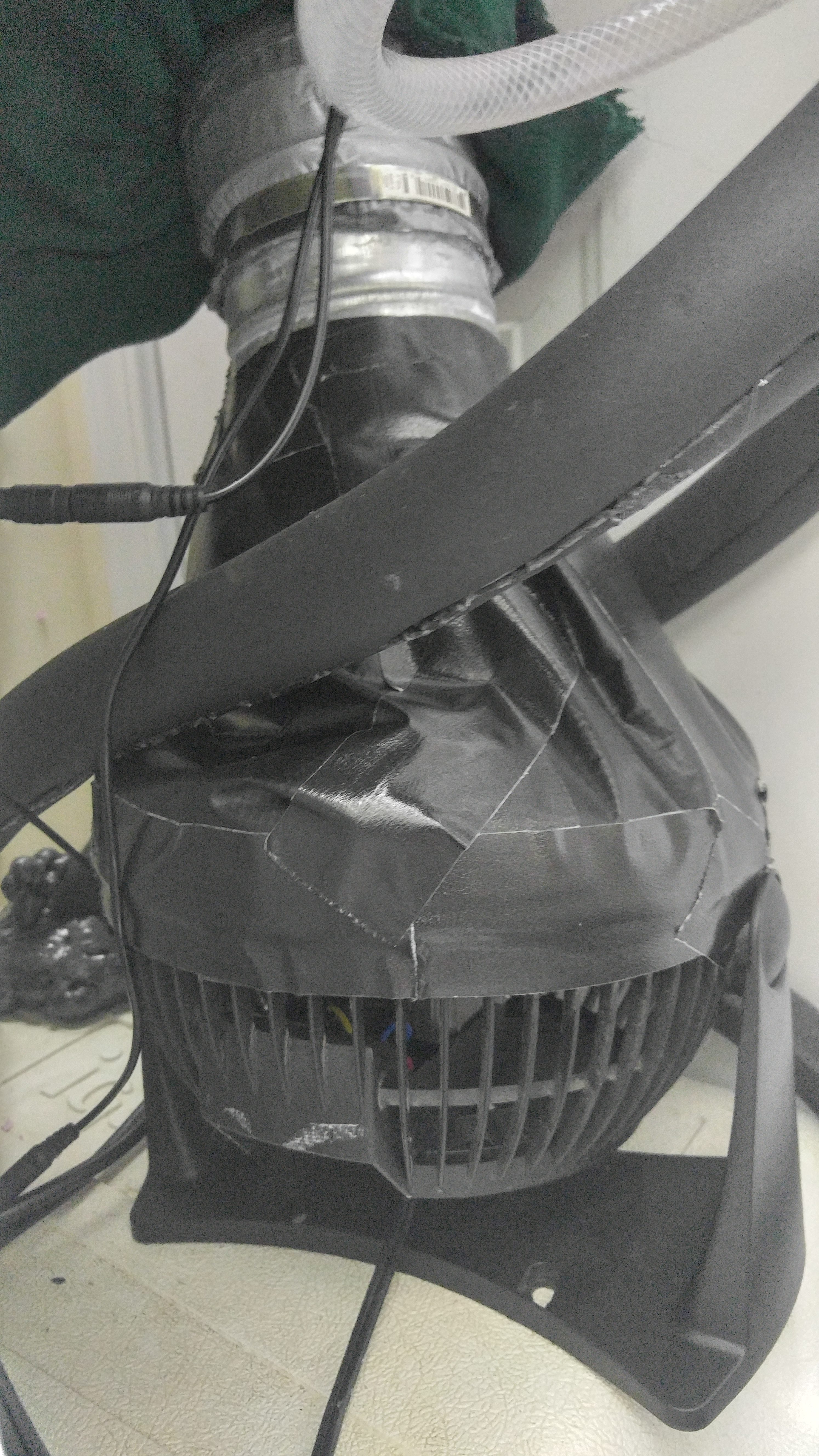
The end result of this rigged fan is that I have a more powerful intake side, which allows day humidity to drop lower to the 80% – 85% levels I am looking to achieve. When I had a 4″ inline fan on the intake side, it was hard to reduce humidity below 90% during the day, so that is why I replaced it with this rigged fan. However, the 4″ inline Apollo fan I mentioned previously would be better.
I have 4″ flexible ducts attached to these fans to be able to direct where the intake and exhaust points are at in my laundry room. This is because I have this box in a very tight space and may not be needed for your setup if your chamber will have good air flow around it. With good air flow, you could simply connect 4″ intake and exhaust fans directly to the 4″ holes on the left / right sides of the chamber.
However, there is one added benefit to having 4″ insulated ducts connected to those holes and then the fans are connected to the ducts – the cold air for the night cooling system has a harder time escaping. If you did want to leave out the ducts, I would at least recommend putting duct dampeners on each side so that those holes would close when the exhaust fans were off at night.

The 10″ fan is on the left side of the chamber and is pointed directly at the left wall but angled slightly upward – the fan is on full power 24/7. The result is an air current that rotates around the box. The fan pulls air from below the shelf and also from the bottom-right (this is where the cold air comes from at night too). That air then bounces off the left wall and ultimately travels across the tops of the plants before it is pulled back down on the right side.
The air current is useful to make sure humidity and temperature levels stay roughly the same throughout the entire box, although the bottom shelf in my setup does seem to stay a degree or two cooler when lights are on.
I also have my environment control sensor on the left side of the box near the fan – you want sensors like that to have good air flow to get acurate readings. Ideally this sensor would be at the same level as the plants. However, direct light and also direct watering can mess up readings (direct water on this sensor is also not recommended – it seems to artificially inflate humidity levels when wet). This is why my sensor hangs below the top shelf. I have a piece of pond liner tarp directly above the sensor, on the shelf, to ensure that water doesn’t fall on it when my automated watering system kicks on.
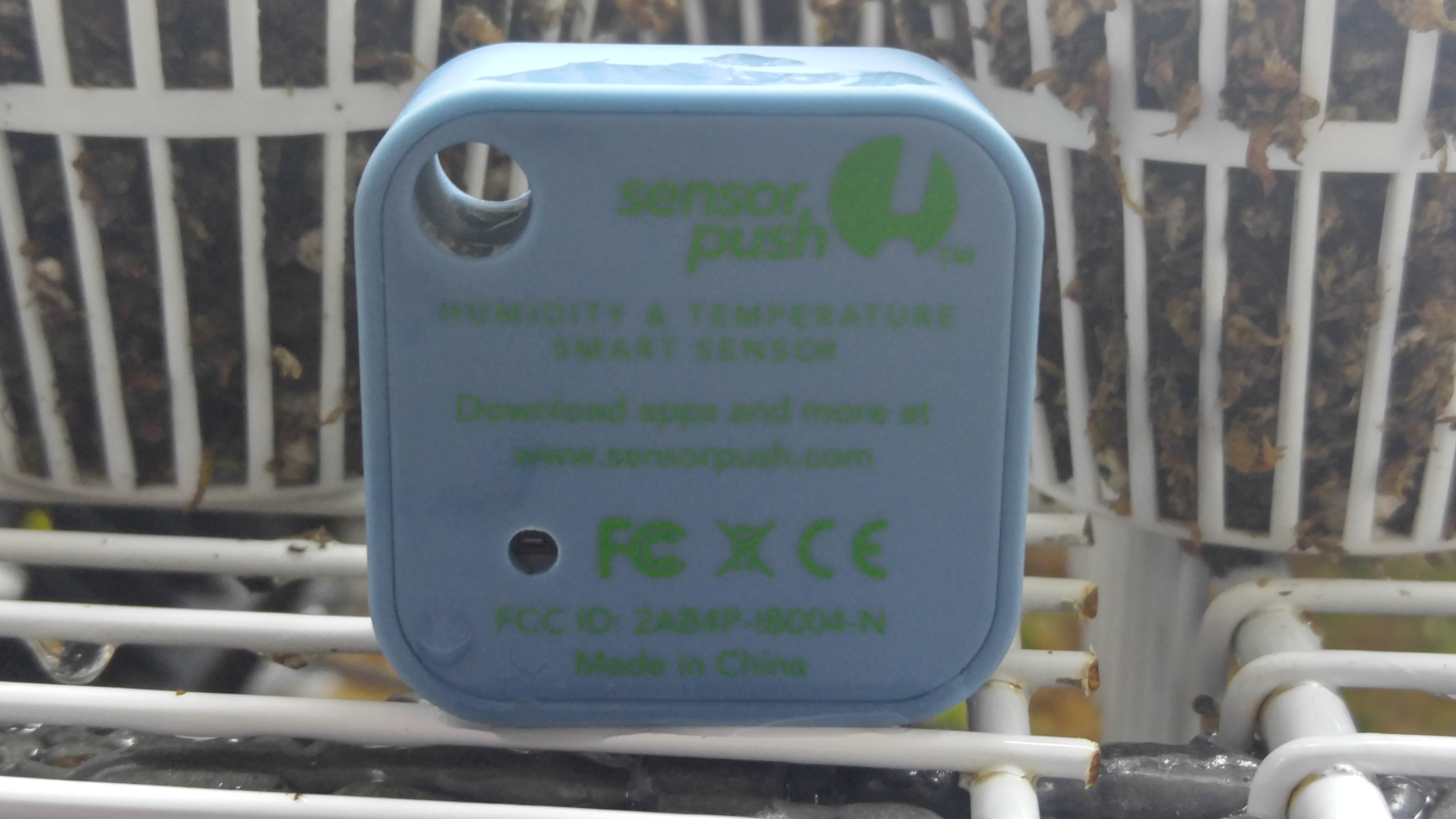
I found a product called SensorPush that solved this for me. This is a temperature and humidity logger that sends the data to your smartphone. Currently, this only works when you are physically in range of the sensor with your phone (about 50′ in a house). However, the phone app can later download data that it missed when not in range.
Sometime in the coming months, they are also supposed to be releasing a WiFi bridge for the SensorPush that will allow it to track your environment over the internet so you don’t need to be in range – this would allow instant monitoring of your plants 24/7 from practically anywhere in the world. I look forward to this being released, but as of now in July 2016 it is not available.
With all of that said about the SensorPush, it is completely optional, but it is a really good way to get a clear picture of your conditions. It is also interesting because you can tell things like how long it takes your cooling system to reach your desired temperature at night, how long it takes to heat back up in the morning, and even how opening your chamber doors affects the conditions.

For my usage and placement, this light vent fan is very necessary to keep temperatures from rising into the 80s or potentially even higher. The air movement across the top of the plexiglass also helps to keep that surface cool, which helps prevent heat transfer into the box.
If your chamber is in a wide-open room, you would likely not need to worry about having a fan on top unless you wanted the lights to be a lot closer than mine (they’re about 10″ – 12″ above the box). However, if you notice day temps rising too high, adding a fan to remove heat from the T5 lights can be an easy and cheap way to solve that problem.
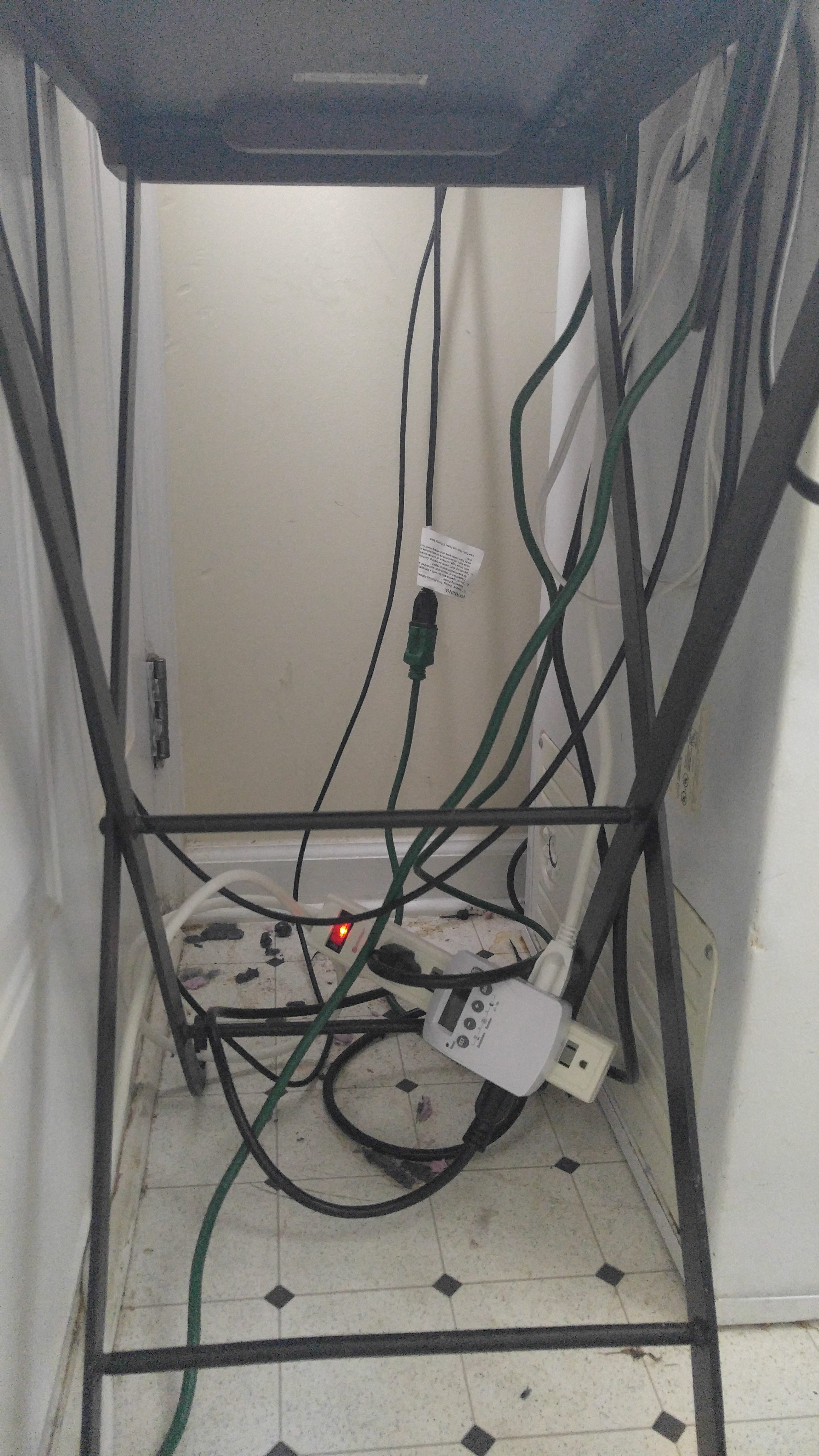
A large majority of these cords and surge protectors ended up going underneath my chamber since the box feet provided about 5″ of open space there. As long as you’re confident that yours won’t be leaking water, you can put them there too. If you have a lot more space to work with than I did, you could also put your electronics behind / to the side of the chamber.
I ended up using 4 different surge protectors, 2 timers and 3 short extension cords for my setup (which also includes the cooling and watering system that have not yet been covered in this guide – those parts are actually on separate pages).
A large majority of these cords and surge protectors ended up going underneath my chamber since the box feet provided about 5″ of open space there. As long as you’re confident that yours won’t be leaking water, you can put them there too. If you have a lot more space to work with than I did, you could also put your electronics behind / to the side of the chamber.
I have my T5 lights and the two daytime 4″ exhaust fans connected to a timer that runs 14 hours on and 10 hours off. The fan inside the box is connected to run 24/7.
Everything else that I’ve covered so far gets connected to the Sentinel DEC – for now, this is really just two ultrasonic humidifiers (one on each side of the box). These are connected the humidity outlet on the DEC so they will cut on if humidity gets too low. Once the cooling system is connected, that will also plug into the DEC in the cooling outlet.